Beyond the Screen: Your First Code-to-Logic Bridge with Arduino
Stop just writing code; start making things move. A software developer's guide to the Arduino Uno, C++ for hardware, and building your first physical Hello World.
Read More →
* SYSTEM.NOTICE: Affiliate links support continued laboratory research.
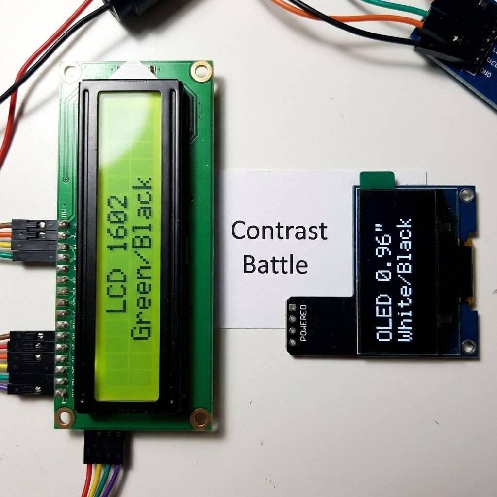
We will focus on the two most popular displays in the maker world:
Liquid Crystal Display technology is fascinating physics. Liquid Crystals are a weird state of matter. They flow like a liquid but line up like a crystal.
Why is it called “1602”? It’s not a model number. It’s the dimensions.
The Backlight: That green glow is just an LED array behind the glass. If you pull the Jumper Cap on the back of the I2C backpack, you physically cut power to the LEDs. Useful if you are running on batteries and want to save 20mA.
You have seen these everywhere. Vending machines, printers, old alarms. “1602” means 16 Columns, 2 Rows. It can display 32 characters total.
RS, E, D4, D5, D6, D7, VCC, GND, RW, V0, A, K).
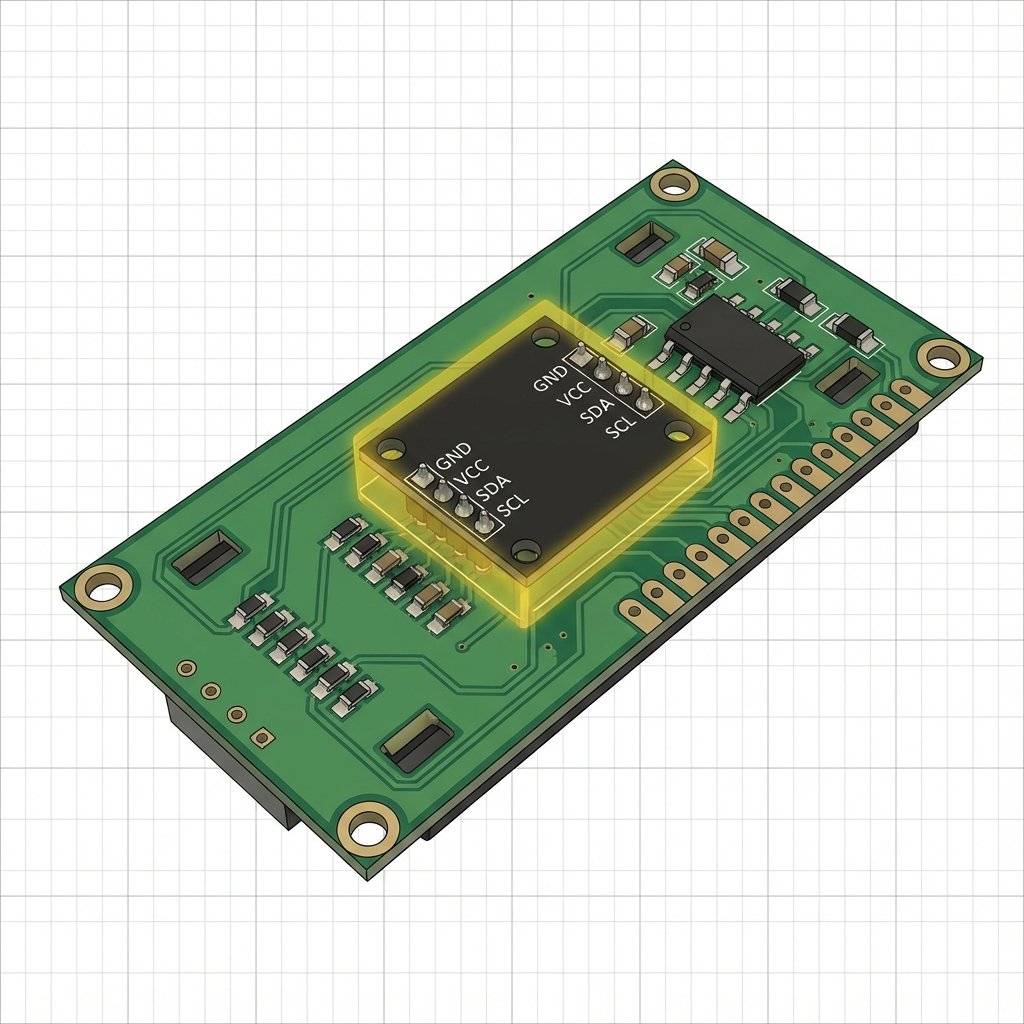
It uses almost every pin on the Arduino Uno. It is a nightmare to wire.VCC, GND, SDA, SCL).Note: If you bought a “Raw” LCD without the black backpack on the back… I am sorry. Go buy the I2C version ($2). It saves your sanity. The backpack uses a chip called the PCF8574 (IO Expander) to turn I2C signals into the 12 parallel signals the LCD needs.
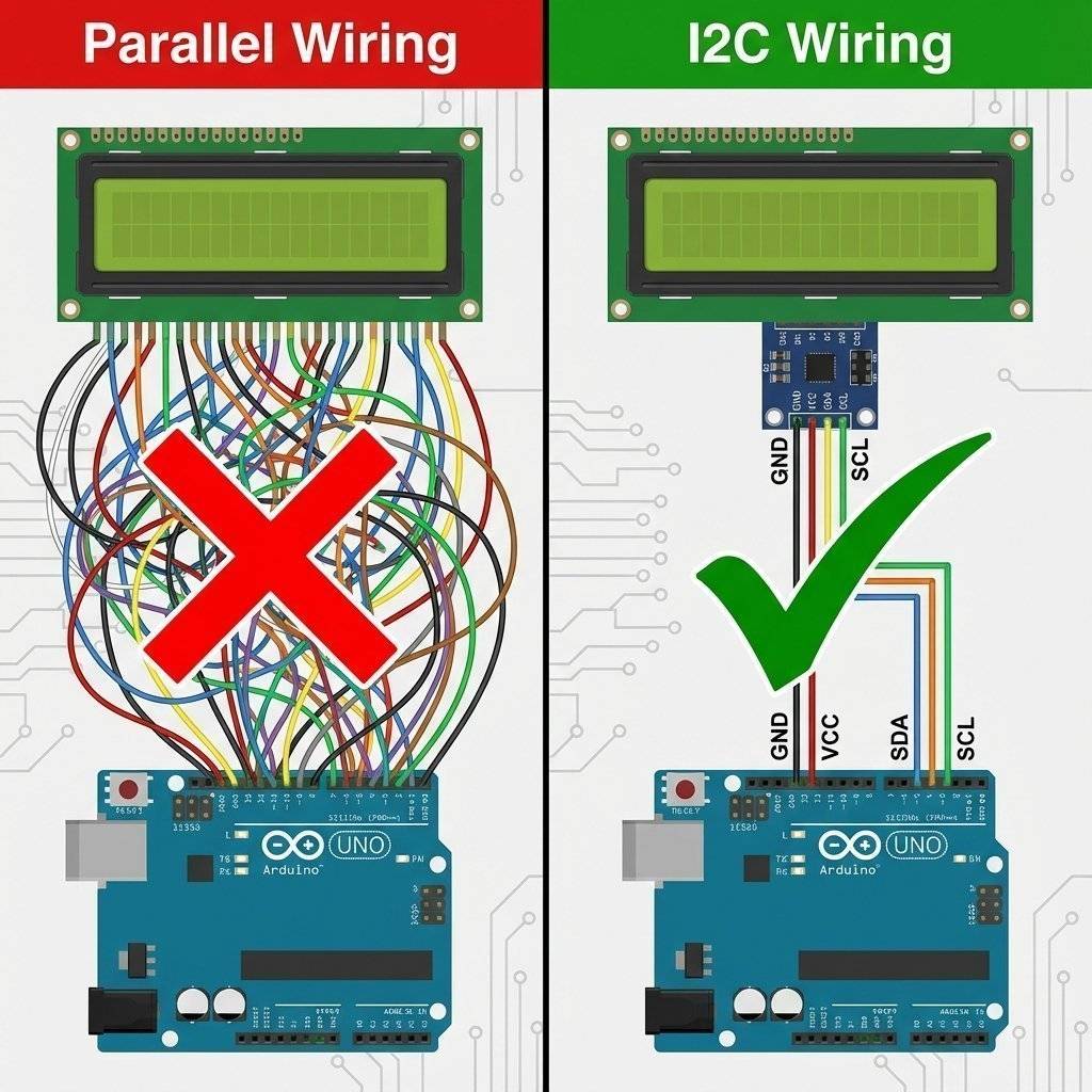
Does this look familiar? It’s the exact same wiring as the RTC from Day 19! I2C is a bus. You can connect the LCD and the RTC to the same two pins.
Standard I2C speed is 100kHz.
For text, this is fine.
For graphics (OLED), it can be slow.
You can turbocharge your I2C bus to 400kHz by adding this line to setup():
Wire.begin();
Wire.setClock(400000); // Fast Mode
Warning: If you have long wires (>20cm), Fast Mode might cause errors. Stick to 100kHz for stability.
We need the most popular library for this.
Ctrl+Shift+I).LiquidCrystal I2C.#include <Wire.h>
#include <LiquidCrystal_I2C.h>
// Set the LCD address to $0x27$ for a $16$ chars and $2$ line display
// If $0x27$ doesn't work, try $0x3F$
LiquidCrystal_I2C lcd(0x27, 16, 2);
void setup()
{
lcd.init(); // Initialize the LCD
lcd.backlight(); // Turn on the light
lcd.print("Hello, World!");
lcd.setCursor(0, 1); // Column 0, Row 1 (The second row)
lcd.print("I am Arduino.");
}
void loop()
{
// Static message, nothing here
}Troubleshooting: The Blue Potentiometer If you upload this and see Nothing (empty screen): Look at the back of the I2C backpack. There is a blue square with a screw. This controls Contrast. Turn it with a screwdriver until the text appears.
Troubleshooting: The Address (0x27 vs 0x3F)
Digital chips have addresses.
Most PCF8574 chips are at 0x27.
Some PCF8574A chips are at 0x3F.
If your screen stays blank, change lcd(0x27, ...) to lcd(0x3F, ...).
Or use the I2C Scanner from Day 19 to find the truth!
Problem: Garbage Characters on Screen
If your screen shows ¥Ωåß∂ƒ instead of “Hello”:
P0 to RS instead of P1).lcd.begin(16,2) instead of lcd.init(). Different libraries use different start commands.Problem: Dim Backlight
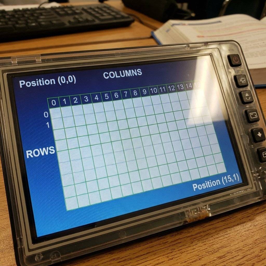
The LCD is a grid.
lcd.setCursor(X, Y) places the invisible “typewriter cursor”.
lcd.setCursor(5, 0) puts it on the 6th character of the top row.
lcd.print() writes text starting at that position and moving right.
The “Ghost” Characters:
The LCD controller actually has memory for 40 characters per line, even though it only shows 16.
If you print 20 characters, the last 4 are “off screen”.
You can use lcd.scrollDisplayLeft() to scroll them into view!
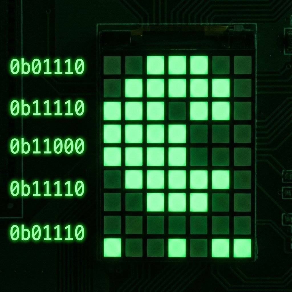
The LCD has a boring font. A, B, C… But it allows you to define up to 8 Custom Characters (0-7). Each character is a 5x8 pixel bitmap.
Let’s make a “Pac-Man” and a “Ghost”.
byte pacman[8] = {
  0b01110,
  0b11101, // Eye
  0b11111,
  0b11100, // Mouth open
  0b11111,
  0b11111,
  0b01110,
  0b00000
};

void setup() {
  lcd.init();
  lcd.backlight();
  lcd.createChar(0, pacman); // Assign bitmap to Slot 0
  lcd.setCursor(0, 0);
  lcd.write(0); // Use write() for special bytes, print() for strings
}
Design Tool: Search online for “LCD Custom Character Generator”. You can click pixels and get the binary code instantly.
A display implies interactivity.
Users expect to push buttons and change settings.
This requires a State Machine.
Don’t use delay(). Use a switch-case.
int page = 0; // 0=Home, 1=Settings, 2=Info

void loop() {
  if (digitalRead(BUTTON_PIN) == LOW) {
    page++;
    if (page > 2) page = 0;
    updateScreen();
    delay(200); // Debounce
  }
}

void updateScreen() {
  lcd.clear();
  switch (page) {
    case 0:
lcd.print("Home Screen");
lcd.setCursor(0,1);
lcd.print("Temp: 24C");
break;
    case 1:
lcd.print("Settings");
lcd.setCursor(0,1);
lcd.print("Set Alarm >");
break;
    case 2:
lcd.print("System Info");
lcd.setCursor(0,1);
lcd.print("Uptime: 42s");
break;
  }
}
This is the skeleton of every UI you have ever used.
LCDs are cheap ($2) and reliable. But they look… retro. If you want “Cyberpunk”, you want OLED.
The Library: Adafruit SSD1306 + Adafruit GFX.
(Note: These libraries are Heavy. They use 1KB of RAM just for the screen buffer. on an Uno with 2KB RAM, this is 50% of your memory! Be careful).
#include <Adafruit_SSD1306.h>

// Screen dimensions
#define SCREEN_WIDTH 128
#define SCREEN_HEIGHT 64

// Declaration for an SSD1306 display connected to I2C (SDA, SCL pins)
Adafruit_SSD1306 display(SCREEN_WIDTH, SCREEN_HEIGHT, &Wire, -1);

void setup() {
  if(!display.begin(SSD1306_SWITCHCAPVCC, 0x3C)) {
    Serial.println(F("SSD1306 allocation failed"));
    for(;;);
  }
  display.clearDisplay(); // Clear buffer

  display.setTextSize(1);
  display.setTextColor(WHITE);
  display.setCursor(0, 10);
  display.println("Hello, OLED!");
  display.drawCircle(64, 32, 10, WHITE); // Draw a circle
  display.display(); // IMPORTANT: Push buffer to screen
}
Critical Rule for OLEDs:
Nothing happens until you call display.display().
All your drawing happens in the Arduino’s RAM (the buffer).
display.display() sends that buffer to the screen over I2C.
If you forget this, the screen stays black.
To draw a complex image (like your startup logo), you need a bitmap.
This is a C-array of hex codes representing pixels.
display.drawBitmap(x, y, myBitmap, width, height, WHITE);
How to generate it:
The GFX library is powerful.
display.drawLine(x1, y1, x2, y2, WHITE);display.drawRect(x, y, w, h, WHITE); (Hollow box)display.fillRect(x, y, w, h, WHITE); (Solid box)display.drawCircle(x, y, r, WHITE);display.drawTriangle(x1, y1, x2, y2, x3, y3, WHITE);Use these to make progress bars or battery indicators!
// Simple Battery Bar
void drawBattery(int percent) {
  display.drawRect(0, 0, 20, 10, WHITE); // Battery body
  display.fillRect(20, 3, 2, 4, WHITE);  // Positive terminal
  int width = map(percent, 0, 100, 0, 18);
  display.fillRect(1, 1, width, 8, WHITE); // Charge level
}
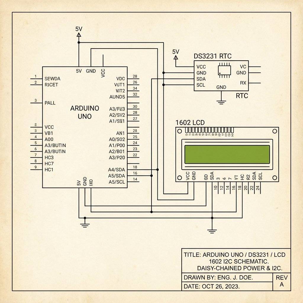
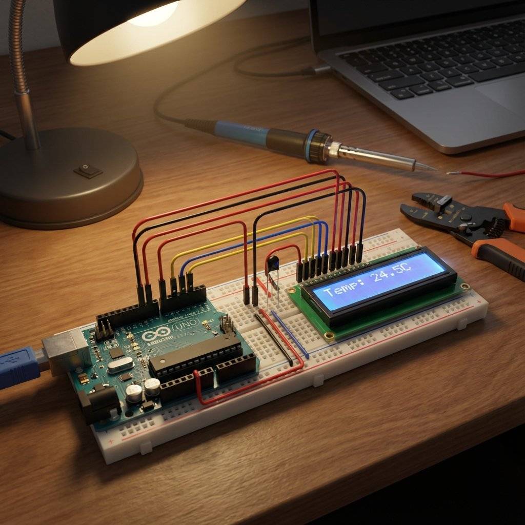
Let’s combine Day 19 (RTC) and Day 20 (LCD). This is a device you can actually put on your desk.
| Component | Quantity | Value | Notes |
|---|---|---|---|
| Arduino Uno | 1 | Any | The Brain. |
| DS3231 RTC Module | 1 | I2C | Real Time Clock. |
| LCD 1602 I2C | 1 | 16x2 | Green or Blue backlight. |
| Jumper Wires | 8 | M-F/M-M | Connectivity. |
Wiring: Daisy chain them! Arduino A4 -> RTC SDA -> LCD SDA Arduino A5 -> RTC SCL -> LCD SCL 5V and GND to both.
The Code (Snippet):
void loop() {
  DateTime now = rtc.now();
  lcd.setCursor(4, 0); // Center the time
  // Leading Zeros trick
  if (now.hour() < 10) lcd.print("0");
  lcd.print(now.hour());
  lcd.print(":");
  if (now.minute() < 10) lcd.print("0");
  lcd.print(now.minute());
  lcd.print(":");
  if (now.second() < 10) lcd.print("0");
  lcd.print(now.second());
  lcd.setCursor(0, 1);
  lcd.print("Temp: ");
  lcd.print(rtc.getTemperature()); // DS3231 has a temp sensor too!
  lcd.print(" C");
  delay(1000);
}A common rookie mistake in loop():
void loop() {
  lcd.clear(); // Wipe screen
  lcd.print(time); // Write new time
  delay(100);
}
Do NOT use lcd.clear() inside a loop.
It takes a long time (milliseconds) to execute. The screen will blink and flicker annoyingly.
Better: Overwrite old data.
If you print “12:00” and then “12:01” on top of it, it looks smooth.
If you need to erase a longer string, print spaces: lcd.print(" ").
You have escaped the Serial Monitor. Your projects are now standalone devices. They can communicate with humans.
This concludes our “Core Modules” arc. We have covered Input (Sensors), Output (Sound, Light, Displays, Motors), and Time. Tomorrow, on Day 21, we enter a new realm. We are going to make the Arduino Think. We will explore State Machines—the logic pattern used to build complex robots and game consoles.

Stop just writing code; start making things move. A software developer's guide to the Arduino Uno, C++ for hardware, and building your first physical Hello World.
Read More →
Arduino pins are digital, so how do they output 2.5V? Learn the secret of Pulse Width Modulation (PWM) to fade LEDs, control motor speed, and mix RGB colors.
Read More →
Stop writing 50 lines of code when 5 will do. We rebuild the iconic Knight Rider scanner using C++ Arrays and For Loops. The ultimate guide to clean coding.
Read More →