Beyond the Screen: Your First Code-to-Logic Bridge with Arduino
Stop just writing code; start making things move. A software developer's guide to the Arduino Uno, C++ for hardware, and building your first physical Hello World.
Read More →
* SYSTEM.NOTICE: Affiliate links support continued laboratory research.
Can a digital pin output a steady 2.5V? If you check the specs of the ATmega328P chip, the answer is a hard NO. It is a digital chip. It can output 0V or 5V. That is it. There is no “2.5V” setting.
So… how do we dim an LED? How do we make a robot move at “Half Speed”? How do we make an RGB light turn purple?
We cheat. We use a technique called Pulse Width Modulation (PWM). We switch the pin ON and OFF so fast that the human eye (or the motor) gets tricked into thinking it sees a lower voltage.
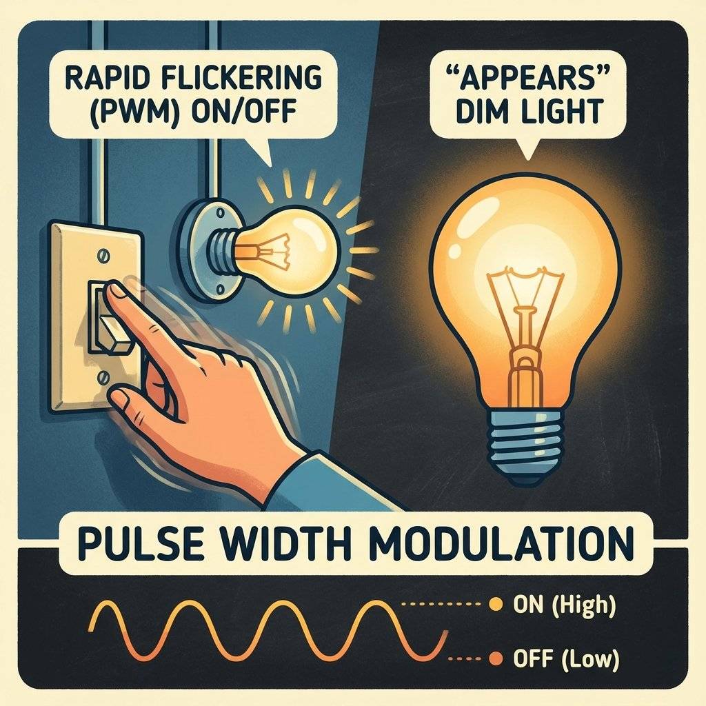
Imagine you have a light switch.
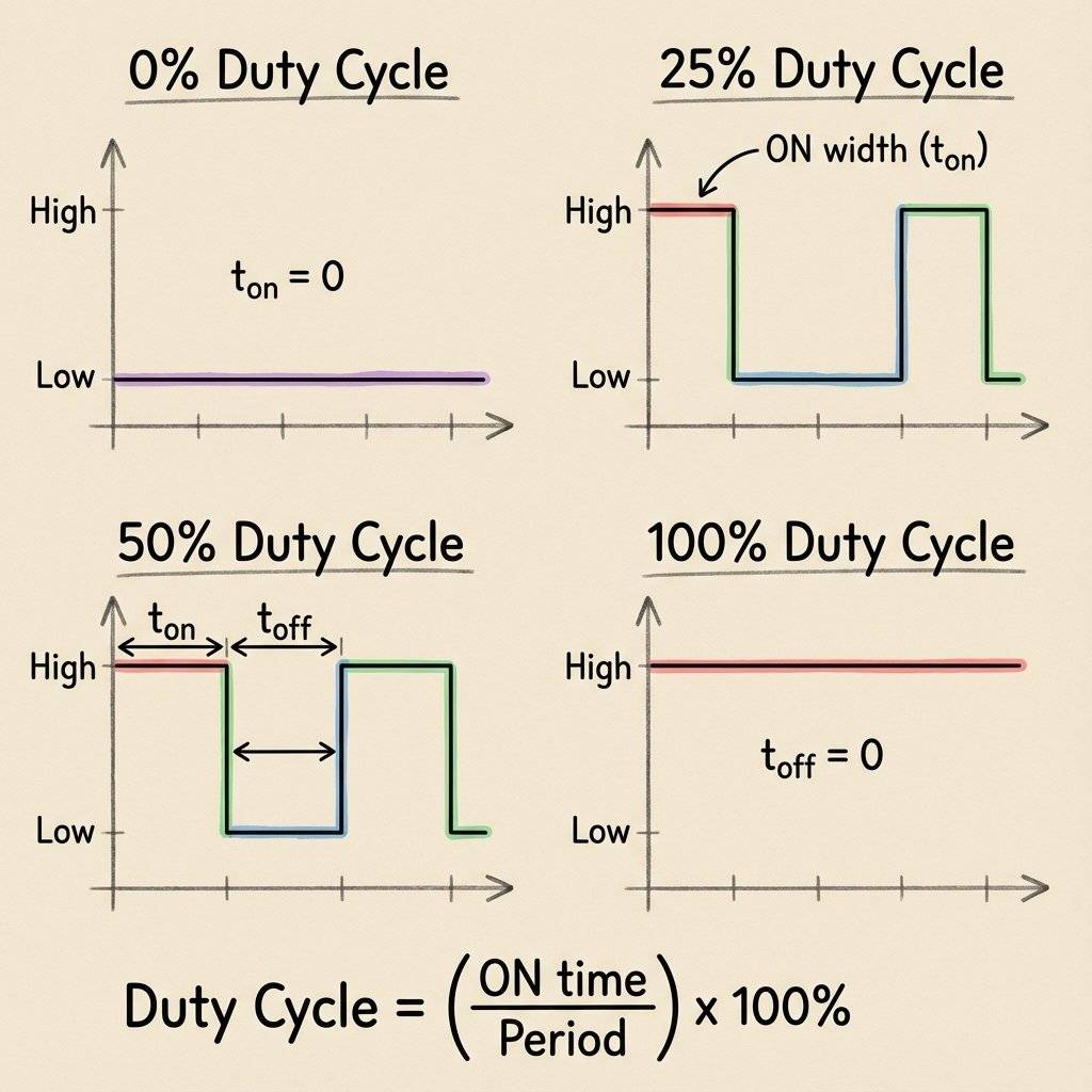
This percentage of “ON Time” is called the Duty Cycle.
analogWrite()To control this, we use the command analogWrite(pin, value).
Wait, why is it called analogWrite if it’s actually digital switching?
Because Arduino likes to keep things simple. It behaves like analog writing.
Unlike analogRead (which is 10-bit, 0-1023), analogWrite is 8-bit.
It accepts a value between 0 and 255.
You cannot use PWM on just any pin.
Look closely at your Arduino board.
Next to pins 3, 5, 6, 9, 10, 11, you will see a tiny wiggle symbol: ~ (Tilde).
These are the PWM-capable pins.
If you try analogWrite(2, 127), nothing will happen (or it will just turn fully ON).
Rule: Always plug fading LEDs into Tilde pins.
What if you run out of PWM pins? Can you use Pin 2? Yes, but you have to do the work yourself. You can write code that manually toggles the pin very fast.
void loop() {
  digitalWrite(2, HIGH);
  delayMicroseconds(500); // ON time
  digitalWrite(2, LOW);
  delayMicroseconds(1500); // OFF time
}
This mimics a 25% duty cycle. The downside? Your code cannot do anything else. This is why hardware PWM (handled by the chip’s internal timers) is superior. It runs in the background while your code calculates other things.

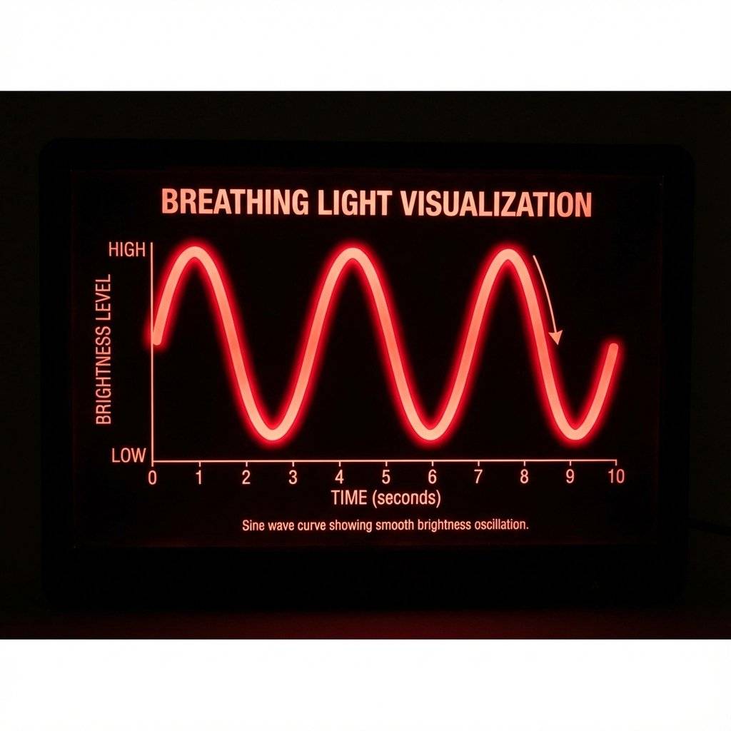
Let’s recreate the classic “Sleep Mode” light from MacBook laptops. It gently fades in and out, like it is breathing.
We need two loops. One to count UP, one to count DOWN.
int ledPin = 9;

void setup() {
  pinMode(ledPin, OUTPUT);
}

void loop() {
  // Fade IN (0 to 255)
  for (int brightness = 0; brightness <= 255; brightness++) {
    analogWrite(ledPin, brightness);
    delay(10); // Wait 10ms for the eye to see it
  }

  // Fade OUT (255 to 0)
  for (int brightness = 255; brightness >= 0; brightness--) {
    analogWrite(ledPin, brightness);
    delay(10);
  }
}
Math check: 255 steps * 10ms = 2550ms (2.5 seconds) to fade up. Total cycle = 5 seconds. A slow, relaxing breath.
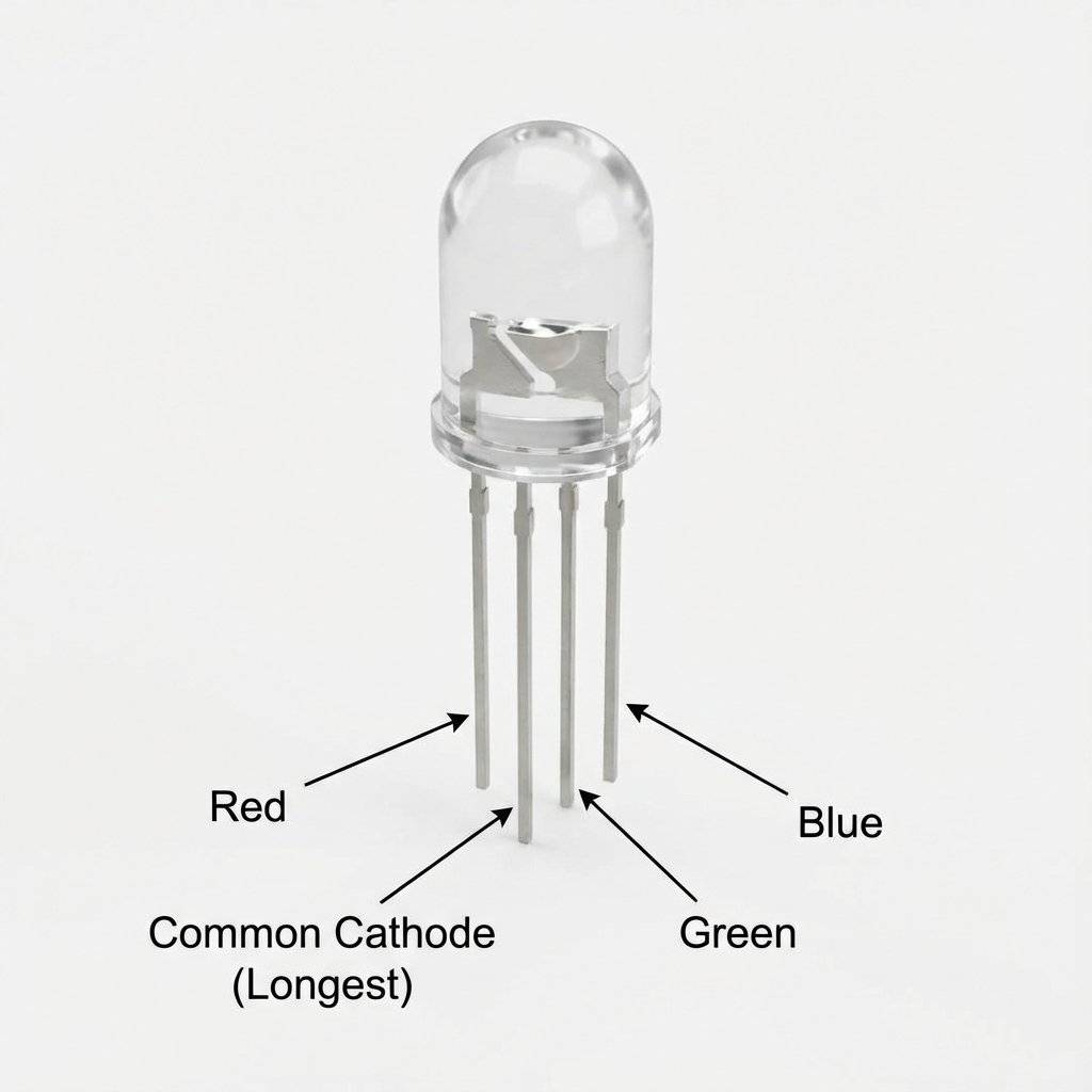
Now that we can dim, we can Mix Colors. An RGB LED is just 3 LEDs (Red, Green, Blue) stuffed into one plastic shell. By fading them at different levels, we can create any color in the rainbow.
It has 4 legs. The Longest Leg is the Common. Check if yours is Common Cathode (connect to GND) or Common Anode (connect to 5V). Most kits have Common Cathode.
int redPin = 9;
int greenPin = 10;
int bluePin = 11;

void setup() {
  pinMode(redPin, OUTPUT);
  pinMode(greenPin, OUTPUT);
  pinMode(bluePin, OUTPUT);
}

void loop() {
  // Make PURPLE (Red + Blue)
  analogWrite(redPin, 255);
  analogWrite(greenPin, 0);
  analogWrite(bluePin, 255);
  delay(1000);

  // Make ORANGE (Full Red + Half Green)
  analogWrite(redPin, 255);
  analogWrite(greenPin, 128); // 50% Green
  analogWrite(bluePin, 0);
  delay(1000);
}
Look at our breathing code again.
delay(10);
It runs 512 times per breath cycle.
That means for 5 seconds, your Arduino is effectively comatose.
It cannot read a button. It cannot check a sensor. It is stuck in the delay().
This is fine for simple toys, but terrible for robots.
The Solution:
Later (Day 21), we will learn millis().
It is like checking a watch (“Is it time to change brightness yet?”) instead of sleeping (“Wake me up in 10ms”).
For now, enjoy the simplicity of delay(), but know that it is a bad habit.
Fading is cool. But Randomness is better. Can you make an LED flicker like a candle in the wind? Hardware: Yellow LED on Pin 9. Code:
void loop() {
  analogWrite(9, random(100, 255));
  delay(random(10, 100));
}
random(min, max) picks a random number.
This creates a jittery, organic light.
Put it inside a translucent cup. You have a safe flameless candle.
You built a breathing light. Now build a Mood Lamp. Goal:
Red -> Green means: Red goes Down, Green goes Up (at the same time).for (int i=0; i<255; i++) {
analogWrite(redPin, 255-i);
analogWrite(greenPin, i);
delay(10);
}If you put this inside a paper lantern, you have a $50 Philips Hue bulb for $2.
Not all PWM pins are created equal.
millis() and delay().
This is why messing with PWM frequencies (advanced hacking) can sometimes break your timing functions.
For LEDs, you won’t notice.
For DC Motors, is often smoother and quieter!| Component | Quantity | Value | Notes |
|---|---|---|---|
| Arduino Uno | 1 | R3 or R4 | The Brain |
| RGB LED | 1 | Common Cathode | The Output |
| Resistors | 3 | - | Current Limiting |
| Jumper Wires | 4 | M-M | Connectivity |
| Breadboard | 1 | Half+ | Prototyping |
Why do we care about fading LEDs?
Because the exact same logic controls Motors.
If you connect a DC motor to a pin (via a Transistor!), analogWrite(127) makes it spin at half speed.
This is how Drones stabilize themselves. They adjust the PWM of each propeller thousands of times a second.
This is how your car’s fan adjusts speed.
PWM is the language of power control.

If you run the fade code above, you might notice something weird. The LED seems to get bright REALLY fast, and then stays bright for a long time. Why? Because the human eye is Logarithmic (just like we learned with Potentiometers yesterday). Twice the power does NOT look like twice the brightness to us. To make a fade look “smooth” to a human, you actually need an Exponential curve. You have to increase brightness slowly at first (1, 2, 4, 8) and fast at the end (…, 64, 128, 255). This math fixes the “Gamma” of the LED. Professional lighting controllers use lookup tables to fix this. For now, just know your eyes are deceiving you.
Here is a physics trick. If you run an LED at 50% Duty Cycle (2.5V effective), does it use 50% Power? Power = Voltage * Current. Or: . Since the Voltage is square-waved, the Average Power is indeed 50%. But the Peak Power is still 100% during the ON phase. This is important for resistors. Even if you dim an LED to 1%, you MUST still use a resistor that can handle 100% current. Because for that tiny 1% slice of time, the full 5V is hitting the LED. Rule: Calculate resistors based on Peak Voltage (5V), never Average Voltage.
When driving Motors with PWM (via a MOSFET), a dangerous thing happens. MOSFETs hate being “halfway” on. They love being Fully ON (0 Resistance) or Fully OFF (Infinite Resistance). During the transition (the rising edge of the square wave), they act like resistors and generate Heat. If you PWM a massive motor at , the MOSFET spends a lot of time in that “transition zone”. It might get hot enough to melt your breadboard. Solution: Use a “Gate Driver” chip to snap the MOSFET on/off instantly, minimizing the transition time. Or just add a heatsink.
It wasn’t invented for LEDs. It was invented for Communication. In the 1940s, ITT engineers used Pulse Time Modulation to squeeze multiple phone calls onto a single wire. By shrinking the pulses, they could fit silence between them for other signals. Today, we use it to drive Class-D Audio Amplifiers (which are 90% efficient compared to old 50% Class-AB amps).
| Symptom | Cause | Solution |
|---|---|---|
| Colors look wrong | Common Anode LED | Invert your logic (255 is OFF) |
| Red is too bright | Efficiency Mismatch | Use for Red, for others |
| LED just blinks | Wrong Pin | Move wire to Pin ~, 3, 5, 6, 9, 10, 11 |
| Flickering Video | Camera Shutter | Reduce shutter speed or increase PWM freq |
Why is the limit 255? Why not 100 or 1000? Because 255 is the maximum value of an 8-bit byte. 2^8 = 256. (0 to 255). The ATMega328 registers are 8 bits wide. To store a value like 256, it would need TWO registers (16 bits). Using 8 bits makes the PWM incredibly fast and memory efficient. We live within the limits of the hardware.
If you want to divide a number by 2 very fast:
Don’t do x / 2.
Do x >> 1.
This shifts the bits to the right.
0000 1000 (8) becomes 0000 0100 (4).
This is how the internal timers handle PWM scaling.
We said PWM controls “Speed”. But for Servo Motors, it controls Position. A Servo expects a pulse every 20ms.
Servo library handles it for you, but under the hood, it is just analogWrite logic running with very precise timing.If you want to control a PC Fan (12V):
analogWrite(128), the MOSFET flickers the Fan’s power 490 times a second.
The fan spins at 50% speed.
This is how every variable-speed drill, fan, and drone works.If you really need a steady 2.5V line (not flickering):
You have mastered the art of the fake.
You can now create smooth transitions, organic pulsing lights, and unlimited colors.
Between digitalWrite (Day 11), analogRead (Day 14), and analogWrite (Day 15), you have complete control over the input and output of energy.
Tomorrow, on Day 16, we combine everything. We will take the following sensors:
See you on Day 16.

Stop just writing code; start making things move. A software developer's guide to the Arduino Uno, C++ for hardware, and building your first physical Hello World.
Read More →
Stop squinting at the Serial Monitor! Learn to connect LCD 1602 (I2C) and OLED SSD1306 displays to Arduino. Master coordinates, custom characters, and build a standalone Digital Clock.
Read More →
Stop writing 50 lines of code when 5 will do. We rebuild the iconic Knight Rider scanner using C++ Arrays and For Loops. The ultimate guide to clean coding.
Read More →