Beyond the Screen: Your First Code-to-Logic Bridge with Arduino
Stop just writing code; start making things move. A software developer's guide to the Arduino Uno, C++ for hardware, and building your first physical Hello World.
Read More →
* SYSTEM.NOTICE: Affiliate links support continued laboratory research.
Today, we solve a real-world problem. We are going to build a Traffic Light Controller.
Visualize an intersection. Cars are rushing from all directions. Pedestrians are waiting. If the lights fail, chaos ensues. People get hurt. The logic must be perfect. It’s not just “Red” and “Green”. It is precise timing. It is sequence. Red -> Green? No. Red -> Green -> Yellow -> Red? Maybe.
In this project, we will move beyond the single LED. We will control three independent outputs. And more importantly, we will learn the single most important concept in programming: The Variable.

We need three LEDs: Red, Yellow (or Amber), and Green. They need to be wired to the Arduino independently.
We could run 6 wires (3 signals, 3 grounds). But we are engineers. We can be efficient. We will use a Common Ground.
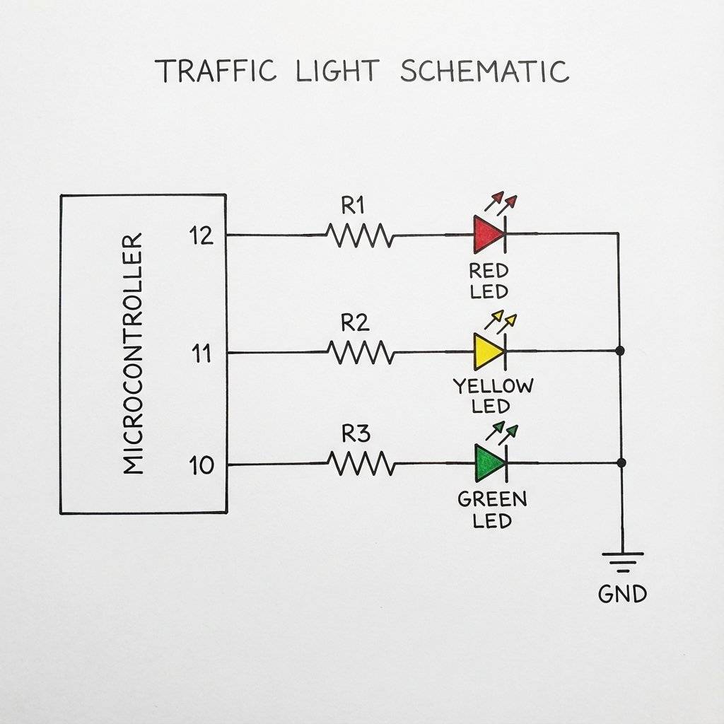
Why 3 resistors? Why not just one resistor on the Common Ground line? Because if you use one shared resistor, the brightness will fluctuate depending on how many LEDs are on. If Red and Yellow are both on, they will be dimmer than if just Red is on. By giving each LED its own resistor (), they maintain consistent brightness.
Before we wrote code, someone had to invent the logic. The first electric traffic light appeared in Cleveland, Ohio in 1914. But the modern 3-position logic is credited to Garrett Morgan, an African-American inventor. He witnessed a terrible accident between a car and a horse-drawn carriage. He realized that just having “Stop” and “Go” wasn’t enough. Drivers needed a warning. He patented the T-shaped traffic signal with a “Wait” position in 1923. General Electric later bought the patent for $40,000. We are essentially programming Garrett Morgan’s logic into silicon today.
Yesterday, we wrote:
digitalWrite(13, HIGH);
What is “13”? To the computer, it’s an address. To a human reading the code in 6 months, it’s a mystery. “What was connected to Pin 13 again? Was it the motor? The alarm?”
Using raw numbers in code is called “Hardcoding” or using “Magic Numbers”. It is bad practice. Imagine you wire your whole city traffic system to Pin 12, 11, 10. Then, you discover Pin 12 is broken. You move the Red light to Pin 9. Now you have to find-and-replace every “12” in your code with “9”. If you miss one… crash.
In C++, a variable is a named container.
We can label a box “RedLight” and put the number “12” inside it.
Then, in our code, we just say:
digitalWrite(RedLight, HIGH);
If we need to change the pin later, we just change the number in the box. The rest of the code updates automatically.
int Data TypeVariables come in types.
So, at the top of our code (before setup), we declare our variables:
int redPin = 12;
int yellowPin = 11;
int greenPin = 10;
You might see tutorials where the Resistor is on the Anode (Positive) side. Others put it on the Cathode (Negative) side. Does it matter? Electrically? No. The current flows through the loop regardless of where the resistor sits. It’s like a kink in a hose. It slows the water down whether it’s at the tap or the nozzle. However, we use a Common Ground layout for cleanliness. We have one single wire going to GND. If we wired it efficiently, we reduce the “spaghetti” on our board. Pro Tip: If you ever work with “RGB LEDs”, they come in two flavors: Common Cathode (Ground) and Common Anode (Voltage). Knowing the difference is critical.
We declared int redPin at the VERY TOP of the file.
This is called a Global Variable.
It means “setup” can see it. “loop” can see it. Everyone can see it.
What if we declared it inside void loop()?
void loop() {
  int counter = 0;
  // ...
}
That would be a Local Variable. It is created when the loop starts. It is destroyed when the loop ends. If the loop restarts, the variable is forgotten and recreated. Rule: For pin definitions, ALWAYS use Global Variables. You want them to exist forever.
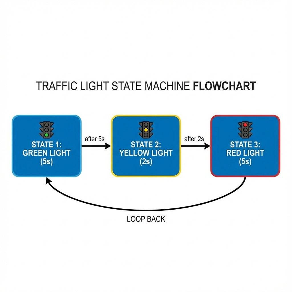
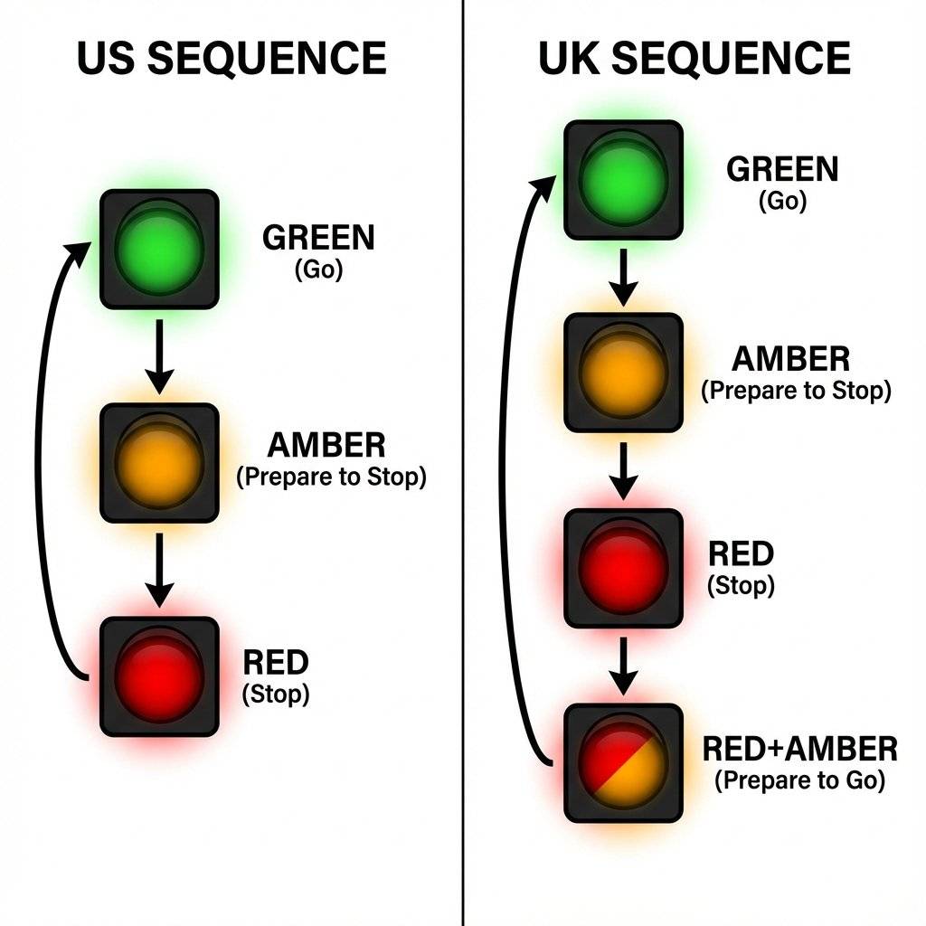
Before we type code, we must define the pattern. How does a traffic light work? It’s a “State Machine”.
Standard US Sequence:
Let’s write it. Open your IDE. Start fresh.
// Project: Traffic Light Controller
// Day 12

// 1. Declare Variables
int redPin = 12;     // Red LED connected to Pin 12
int yellowPin = 11;  // Yellow LED connected to Pin 11
int greenPin = 10;   // Green LED connected to Pin 10

void setup() {
  // 2. Configure Pins
  // We need to tell the Arduino that ALL these pins are outputs
  pinMode(redPin, OUTPUT);
  pinMode(yellowPin, OUTPUT);
  pinMode(greenPin, OUTPUT);
}

void loop() {
  // --- STATE 1: GREEN ---
  // Turn Green ON, others OFF
  digitalWrite(greenPin, HIGH);
  digitalWrite(yellowPin, LOW);
  digitalWrite(redPin, LOW);
  delay(5000); // Wait 5 Seconds. Cars are moving.

  // --- STATE 2: YELLOW ---
  // Turn Yellow ON, others OFF
  digitalWrite(greenPin, LOW);
  digitalWrite(yellowPin, HIGH);
  digitalWrite(redPin, LOW);

  delay(2000); // Wait 2 Seconds. Slow down!

  // --- STATE 3: RED ---
  // Turn Red ON, others OFF
  digitalWrite(greenPin, LOW);
  digitalWrite(yellowPin, LOW);
  digitalWrite(redPin, HIGH);

  delay(5000); // Wait 5 Seconds. Stop.
}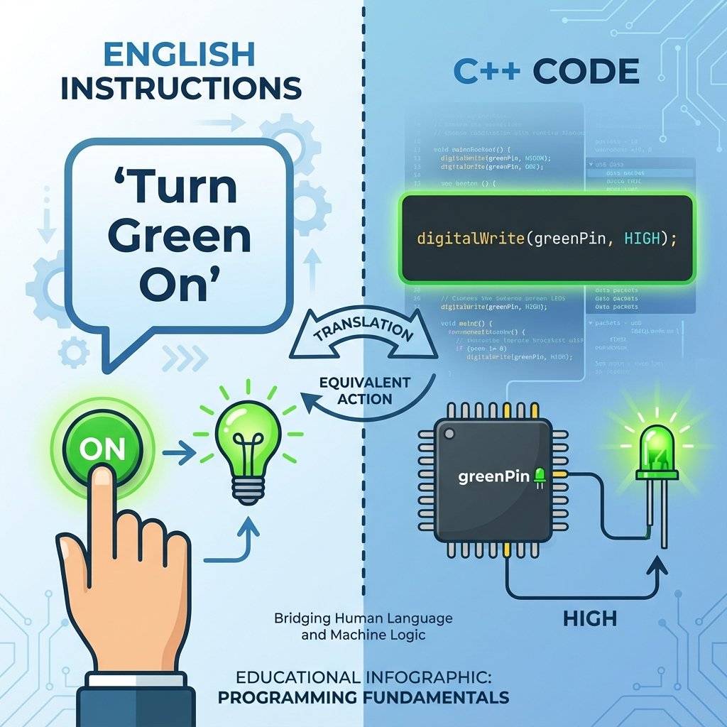
Look at digitalWrite(greenPin, HIGH).
It reads like English.
“Write the Green Pin High.”
Even a non-programmer can look at that and understand the safety logic.
Did you know traffic lights work differently around the world? Our code above mimics the USA/Continental Europe standard. Green -> Yellow -> Red -> Green.
But in the UK (and many Commonwealth countries), there is a “Get Ready” phase. Red -> Red + Amber -> Green. This gives drivers a warning that the light is about to turn green, so they can shift into gear.
Can you modify your code to simulate a London intersection? You need a 4th state.
Try it.
The beauty of software is that you don’t need to change a single wire on your breadboard.
You just type a new digitalWrite.
In the hardware age (using 555 timers from Day 5), changing from US to UK logic would have required tearing the circuit apart and rebuilding it.
Here, it takes 30 seconds.
Here is how you would implement the London-style logic. Notice Step 4. We turn TWO pins HIGH at the same time.
void loop() {
  // 1. GREEN (Go)
  digitalWrite(greenPin, HIGH);
  digitalWrite(yellowPin, LOW);
  digitalWrite(redPin, LOW);
  delay(5000);

  // 2. AMBER (Stopping)
  digitalWrite(greenPin, LOW);
  digitalWrite(yellowPin, HIGH);
  digitalWrite(redPin, LOW);
  delay(2000);

  // 3. RED (Stopped)
  digitalWrite(greenPin, LOW);
  digitalWrite(yellowPin, LOW);
  digitalWrite(redPin, HIGH);
  delay(5000);

  // 4. RED + AMBER (Get Ready)
  digitalWrite(greenPin, LOW);
  digitalWrite(yellowPin, HIGH); // ON
  digitalWrite(redPin, HIGH);    // ON
  delay(1500);
}
This demonstrates the power of the microcontroller. Complex logic (two lights on, then one off) is trivial.
In the real world, “Traffic Controllers” are Life-Safety Systems. If the Microcontroller freezes, people die. Real traffic lights have a hardware monitor called a Conflict Monitor Unit (CMU).
// Safety Check
if (digitalRead(greenNorth) == HIGH && digitalRead(greenEast) == HIGH) {
    emergencyShutdown();
}
This is Defensive Programming. You assume your code will fail, and you plan for it.
Can you simulate a FULL intersection? Imagine North-South Logic vs East-West Logic.
digitalWrite commands to synchronize them.
Safety Check: Ensure Green never overlaps!
This is your homework for tonight.delay() FunctionI have a confession.
The code we wrote today has a fatal flaw.
It relies on delay().
delay(5000) tells the processor: “Go to sleep for 5 seconds. Do nothing. Ignore the world.”
What if we wanted to add a Pedestrian Button?
If a pedestrian presses the button while the light is Green (during the 5000ms delay), the Arduino won’t see it.
It is asleep.
It will only check inputs after it wakes up.
This is called “Blocking Code”.
For a simple traffic light, it’s fine.
But for a robot or a game, it is a disaster.
In a few days (Day 15), we will learn the professional solution: millis().
millis() allows the Arduino to “multitask” (check a watch) instead of sleeping.
But for today, enjoy the simplicity of the delay.
LOW commands? Remember, digitalWrite is “Sticky”. If you turn a pin HIGH, it stays HIGH until you explicitly tell it to go LOW.RedPin is different from redPin.This simple project exposes a massive flaw in linear programming.
Imagine we added a button to Pin 2.
We want the light to turn Green IMMEDIATELY when the button is pressed.
With our current code (delay(5000)), if you press the button 0.1 seconds after the delay starts, the Arduino ignores you for 4.9 seconds.
This is unacceptable for safety.
In a real traffic controller, there is no “delay”.
There is a State Machine.
It constantly checks:
delay() is a training wheel. Eventually, we must take it off.Cause: You inserted the resistor into the wrong row, bridging the connection. Check your breadboard rows (a-e and f-j are separated by the ravine).
Cause: Your USB cable might be loose, or your laptop port is providing low current. Try a different USB port.
Cause: You selected “Arduino Uno” but you have a “Nano” or “Mega” selected in the Tools menu. Double check!
Variable: A named storage location in memory.
Integers (int): Whole numbers.
Hardcoding: Using specific values (like ‘13’) directly in logic code. Bad practice.
Sequence: A specific order of operations.
State Machine: A system that relies on distinct phases (Green, Yellow, Red).
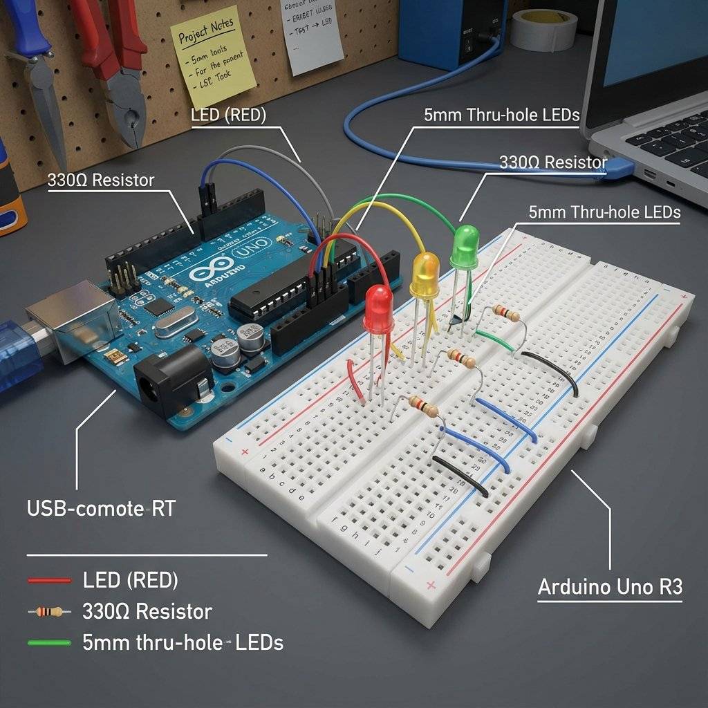
| Component | Quantity | Value | Notes |
|---|---|---|---|
| Arduino Uno | 1 | R3 or R4 | The Brain |
| LED | 1 | Red | Traffic Light |
| LED | 1 | Yellow/Amber | Traffic Light |
| LED | 1 | Green | Traffic Light |
| Resistor | 3 | - | Current Limiting |
| Jumper Wires | 4 | M-M | Connectivity |
| Breadboard | 1 | Half+ | Prototyping |
You have modeled reality. You took a physical concept (Safety logic) and translated it into C++. You learned that Variables are not just for math—they are for legibility. They make your code human-readable.
Tomorrow, on Day 13, we are going to revisit an old friend. Remember the Knight Rider Scanner from Day 10? It required two chips and a mess of wires. Tomorrow, we will build it with the Arduino. We will learn about Arrays and For Loops to create complex animations with just a few lines of code.
See you on Day 13.

Stop just writing code; start making things move. A software developer's guide to the Arduino Uno, C++ for hardware, and building your first physical Hello World.
Read More →
Stop squinting at the Serial Monitor! Learn to connect LCD 1602 (I2C) and OLED SSD1306 displays to Arduino. Master coordinates, custom characters, and build a standalone Digital Clock.
Read More →
Arduino pins are digital, so how do they output 2.5V? Learn the secret of Pulse Width Modulation (PWM) to fade LEDs, control motor speed, and mix RGB colors.
Read More →