Beyond the Screen: Your First Code-to-Logic Bridge with Arduino
Stop just writing code; start making things move. A software developer's guide to the Arduino Uno, C++ for hardware, and building your first physical Hello World.
Read More →
* SYSTEM.NOTICE: Affiliate links support continued laboratory research.
For the last 10 days, you have been a Hardware Engineer. You built logic with wires. To make a light blink, you chose a capacitor and a resistor. To make it blink faster, you had to physically rip out the capacitor and replace it. To change the pattern, you had to rewire the whole board.
It was powerful. But it was rigid.
Today, you become a Software Engineer. We are going to introduce a brain. A chip that can rewire itself instantly. A chip that listens to commands. A chip that thinks.
This is the Arduino Uno. And by the end of this post, you will write your first line of code.
Imagine you are building a house.
Hardware (Days 1-10): You are laying bricks. If you want to move a window, you have to smash the wall.
Software (Days 11-20): You are playing Minecraft. If you want to move a window, you just click.
The Microcontroller (the chip on the Arduino) allows us to change the behavior of electricity using text. Instead of soldering a new circuit to change a heavy machine press into a delicate robot arm, we just upload a new file.
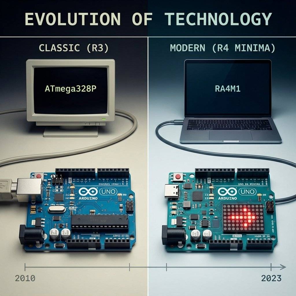
The board you are holding is the Arduino Uno (probably the R3 or the new R4 Minima). It is the most popular educational computer in history. Let’s tour the city.
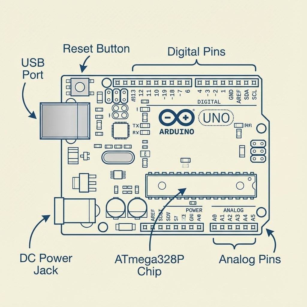
That long black chip in the middle? That’s the Microcontroller.
CPU: (It thinks 16 million times per second).
Flash Memory: 32KB (Where your code lives).
RAM: 2KB (Short term memory). Yes, your phone has 8GB of RAM. The Arduino has 2KB. But the Arduino doesn’t run Windows. It runs raw metal. It is fast enough to control a rocket engine.
These are the black sockets on the side. This is where the real world connects to the brain.
If you bought a board recently, you might have the Uno R4. It is 3x faster (), has of RAM (16x more!), and has a built-in LED matrix. Don’t worry. The code we write today works on both. C++ is eternal.
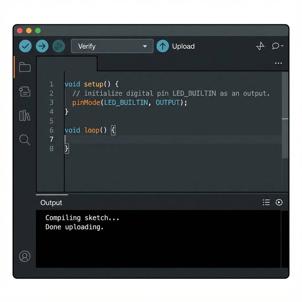
The hardware is a brick without instructions. We write those instructions in the Arduino IDE (Integrated Development Environment).
Download it: Go to arduino.cc and grab IDE 2.0+.
Plug it in: Connect your Uno to your USB port.
Select Board: In the dropdown, pick “Arduino Uno” and the correct COM port.
The IDE has two main buttons:
Checkmark (Verify): “Did I make any typos?”
Arrow (Upload): “Send this to the chip!”
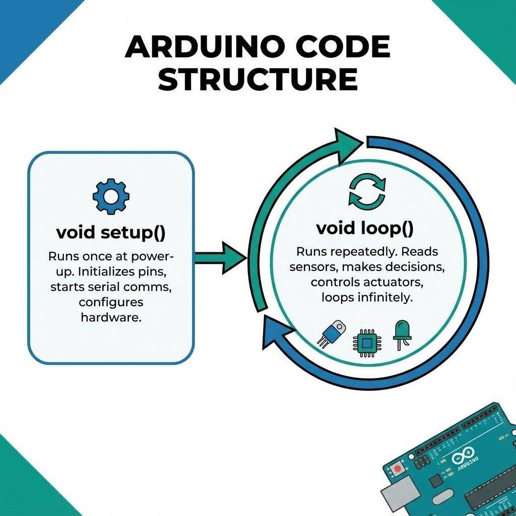
Arduino code (called a “Sketch”) is based on C++. It has a very specific structure. Every Arduino program has two main functions. No exceptions:
void setup() {
  // Put your setup code here, to run once:
}

void loop() {
  // Put your main code here, to run repeatedly:
}This runs ONCE when you power up the board. It is the morning routine. Wake up. Put on shoes. Open the door. We use it to tell the chip which pins we are using. “Hey, Pin 13 is going to be an Output today.”
This runs FOREVER. It runs top to bottom, then jumps back to the top. Start -> Do A -> Do B -> Do C -> Go to Start. This is where the magic happens. If you want an LED to blink, you turn it on, wait, turn it off, wait, and repeat.
It is a strange name. The project started in 2005 at the Interaction Design Institute Ivrea (IDII) in Italy. The founders wanted a cheap way for design students to build prototypes. At the time, microcontrollers were expensive and difficult to program. They met at a bar in Ivrea called Bar di Re Arduino (Bar of King Arduin). So they named the board after the bar. The project was “Open Source Hardware”. This was revolutionary. It meant anyone could copy the design, build their own board, and sell it. Instead of killing the company, it made the platform explode. Today, there are thousands of Arduino clones, but the official blue board is still the icon.
You might wonder: “Why do we use C++? Why not Python?” Python is easy. C++ is hard. Answer: Efficiency. The Arduino has 2KB of RAM. Python needs an interpreter (a program running in the background) to read your code. That interpreter takes up megabytes of RAM. It wouldn’t fit. C++ is a “Compiled Language”. When you verify your code, your powerful PC translates it into raw machine code (Binary). That resulting binary is tiny and efficient. It speaks directly to the silicon without a translator. This allows the Arduino to react in microseconds, which is critical for timing-sensitive electronics.
The most common error for beginners is forgetting the semicolon.
In English, a period . ends a sentence.
In C++, a semicolon ; ends a command.
If you forget it, the compiler panics. It doesn’t know where the command ends.
It’s like reading a book without punctuation.
Rule of thumb: If the line doesn’t end with a { or }, it probably needs a ;.
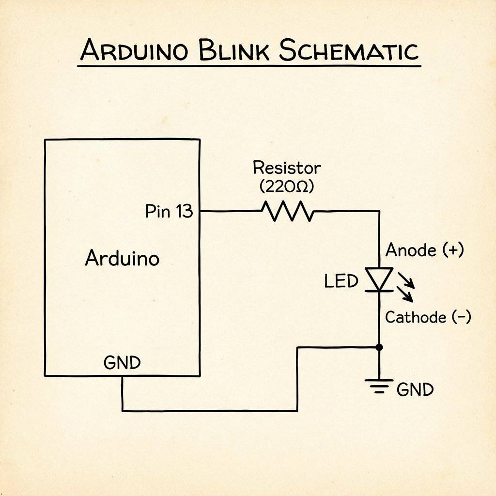
The “Hello World” of electronics. We will make the built-in LED (connected to Pin 13) blink.
Copy this code into your IDE:
// Day 11 Blink Sketch

void setup() {
  // Initialize Pin 13 as an Output
  // "LED_BUILTIN" is a shortcut for Pin 13
  pinMode(LED_BUILTIN, OUTPUT);
}

void loop() {
  digitalWrite(LED_BUILTIN, HIGH);  // Turn LED ON (5V)
  delay(1000);                      // Wait 1000ms (1 second)
  digitalWrite(LED_BUILTIN, LOW);   // Turn LED OFF (0V)
  delay(1000);                      // Wait 1000ms
}
Let’s translate C++ to English.
pinMode(LED_BUILTIN, OUTPUT);
The Command: “Configure a pin.”
digitalWrite(LED_BUILTIN, HIGH);
The Command: “Write a digital value.”
Action: Connect Pin 13 to +5V internal rail.
Result: Current flows. LED lights up.
delay(1000);
The Command: “Freeze.”
Action: Stop thinking for 1000 milliseconds.
Why? If we didn’t wait, the chip runs at . It would turn on and off 8 million times a second. The LED would just look dim. We need to slow it down for human eyes.
digitalWrite(LED_BUILTIN, LOW);
Action: Connect Pin 13 to GND (0V).
Click the Arrow Button. You will see some text scrolling at the bottom (“Compiling… Uploading…”). Watch your board. The little “TX” and “RX” LEDs will flash rapidly (that’s the data flowing over USB). Then… Silence. And then… Blink. Blink. Blink. The “L” LED near Pin 13 is alive.
Congratulations. You are a programmer.
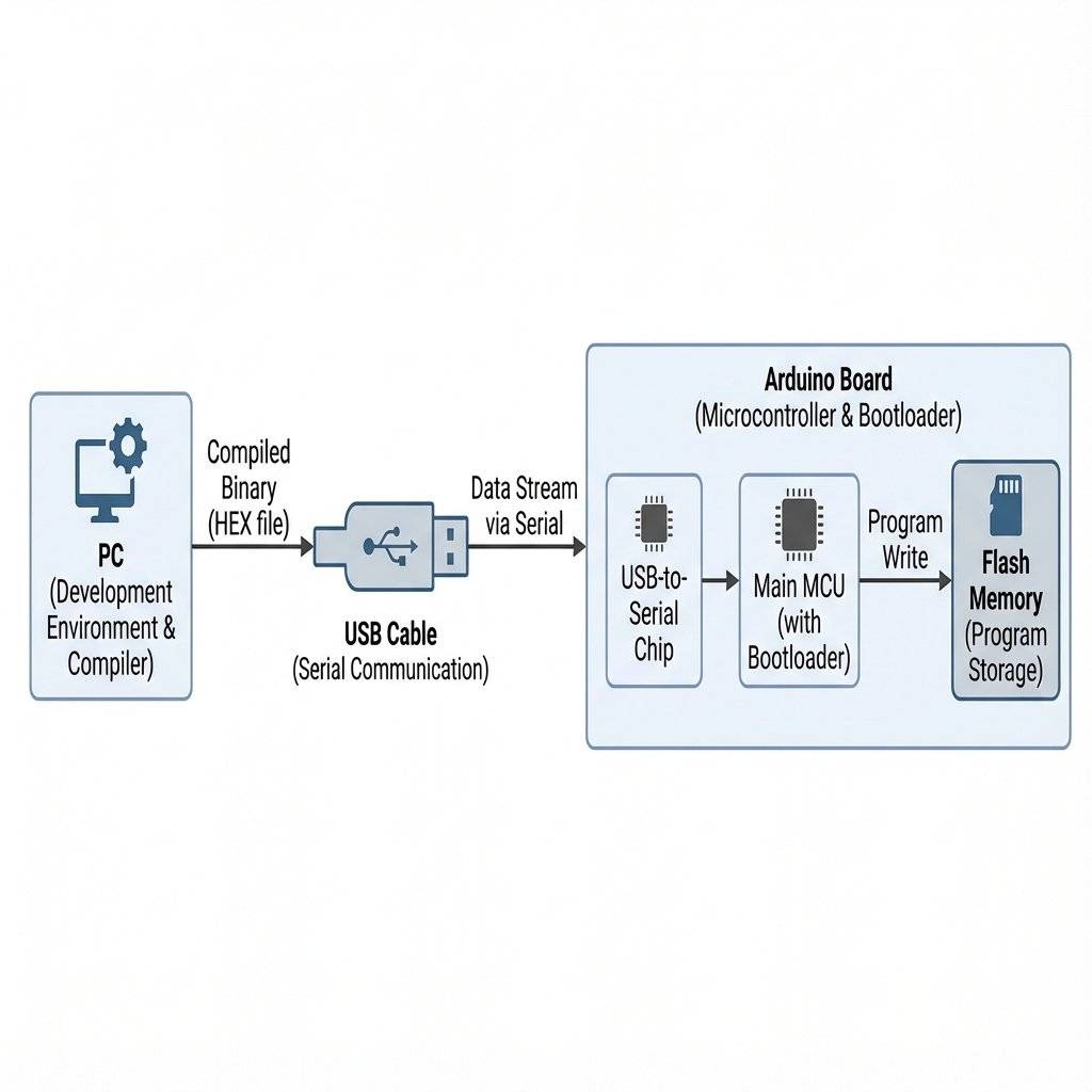
When you clicked “Upload”, a lot happened in 2 seconds.
Preprocessor: The IDE grabbed your code and added some hidden C++ headers.
Compiler: A program called avr-gcc translated your text (digitalWrite) into Machine Code (0s and 1s).
Linker: It combined your code with the Arduino core libraries.
Uploader: A tool called avrdude talked to the USB chip on the board.
Bootloader: A tiny program already on the Arduino woke up, grabbed the new code coming from USB, and wrote it into the Flash Memory.
Reset: The chip rebooted and started running your new code.
All of that complexity is hidden from you. That is the beauty of Arduino.
Why don’t we need an expensive “Programmer” device to load code? Because of the Bootloader. This is a small 512-byte program that lives permanently in the secure area of the flash memory. When the chip resets, the Bootloader runs first. It shouts: “Hey! Is anyone trying to send me code over USB?”
What happens if your code freezes? In a satellite or a medical device, you can’t just press the reset button. The ATmega328P has a Watchdog Timer. It is a separate countdown clock. Your code must “pet the dog” (reset the timer) constantly. If your code crashes and forgets to pet the dog, the timer hits zero and bites the CPU (forces a hard reset). We will learn how to use this advanced safety feature in Part 3.
delay(1000) -> Wrong
delay(1000); -> RightGetting the IDE ready is 50% of the battle. For Windows Users:
.exe installer from arduino.cc.For Mac Users:
.dmg.For Linux Users:
sudo apt-get install arduino does.dialout group: sudo usermod -a -G dialout $USER. Otherwise, you won’t have permission to talk to the USB port.Arduino code (called a “Sketch”) is based on C++. You have a working blink. Now, Science starts. Change the code to see what happens.
delay(1000) to delay(100). Does it strobe?100 and the OFF time to 1000. Does it look like a flash?Hint: You will need to copy paste the digitalWrite lines multiple times inside the loop.
To save you some frustration, here is how you write S.O.S (Save Our Souls). S: 3 Short Blinks. O: 3 Long Blinks. S: 3 Short Blinks.
void loop() {
  // S (Short, Short, Short)
  digitalWrite(13, HIGH); delay(200); digitalWrite(13, LOW); delay(200);
  digitalWrite(13, HIGH); delay(200); digitalWrite(13, LOW); delay(200);
  digitalWrite(13, HIGH); delay(200); digitalWrite(13, LOW); delay(200);
  delay(1000); // Wait between letters (Gap)

  // O (Long, Long, Long)
  digitalWrite(13, HIGH); delay(600); digitalWrite(13, LOW); delay(200);
  digitalWrite(13, HIGH); delay(600); digitalWrite(13, LOW); delay(200);
  digitalWrite(13, HIGH); delay(600); digitalWrite(13, LOW); delay(200);

  delay(1000); // Wait between letters

  // S (Short, Short, Short)
  digitalWrite(13, HIGH); delay(200); digitalWrite(13, LOW); delay(200);
  digitalWrite(13, HIGH); delay(200); digitalWrite(13, LOW); delay(200);
  digitalWrite(13, HIGH); delay(200); digitalWrite(13, LOW); delay(200);

  delay(3000); // Wait before repeating the message
}
Notice how long and messy that code is? That is bad programming. We are repeating ourselves. In Part 2 (specifically Day 13), we will learn about FOR Loops to make this cleaner.
Microcontroller: A small computer on a single integrated circuit.
IDE: Integrated Development Environment. The software where we write code.
Sketch: The name for an Arduino program.
Compile: Converting human-readable code into machine-readable instructions.
GPIO: General Purpose Input Output. The pins we can control.
Function: A block of code that performs a specific task (setup, loop).
Variable: A container for storing data values (we will use these tomorrow).
The Arduino is more robust than a CMOS chip, but it is not invincible.
You have entered Part 2. Here is the plan.
You have killed the wiring. To change the blink speed in Day 5 (555 Timer), you had to calculate , find a new capacitor, and solder it in. Today, you just deleted a “0” and typed a “1”.
This is the power of Software Defined Hardware. But blinking an LED is just the beginning. Tomorrow (Day 12), we are going to use variables and logic to build a Traffic Light Controller. We will model the real world. And we won’t need a single new chip. Just code.
One final secret.
The real power of Arduino isn’t the hardware. It’s the Libraries.
Thousands of people have written code for every sensor imaginable.
Want to read a GPS? #include <TinyGPS.h>.
Want to drive a screen? #include <LiquidCrystal.h>.
You don’t have to reinvent the wheel. You just have to know how to install the wheel.
We will explore this power soon.
See you on Day 12.

Stop just writing code; start making things move. A software developer's guide to the Arduino Uno, C++ for hardware, and building your first physical Hello World.
Read More →
Stop squinting at the Serial Monitor! Learn to connect LCD 1602 (I2C) and OLED SSD1306 displays to Arduino. Master coordinates, custom characters, and build a standalone Digital Clock.
Read More →
Arduino pins are digital, so how do they output 2.5V? Learn the secret of Pulse Width Modulation (PWM) to fade LEDs, control motor speed, and mix RGB colors.
Read More →