The Great Restrictor: Mastering Resistance & Ohm's Law
Stop burning out your LEDs. Master electrical resistance, Ohm's Law calculations, and build your first protected circuit in Day 3 of our Electronics series.
Read More →
* SYSTEM.NOTICE: Affiliate links support continued laboratory research.
Welcome to Day 3.
If Day 1 was the orientation and Day 2 was the theory, today is the Lab. Today, we stop imagining electricity and start manipulating it. Today, electrons will obey your commands for the very first time.
We are going to introduce you to the two best friends you will ever have in this hobby:
And by the end of this post, you will have built the “Hello World” of hardware: The LED Circuit.
Look at it. It’s a white block of plastic with hundreds of tiny holes. To the beginner, it looks like random chaos. “Where do I plug the wire? Does it matter?” To the engineer, it is an organized grid of hidden connections.
A Breadboard is just a bunch of fancy hidden wires.
You don’t need to solder anything. You just push a wire in, and a spring clip grabs it. Pull it out, and the connection is broken. Ideally suited for prototyping.
The breadboard is split into two distinct zones. They work completely differently.
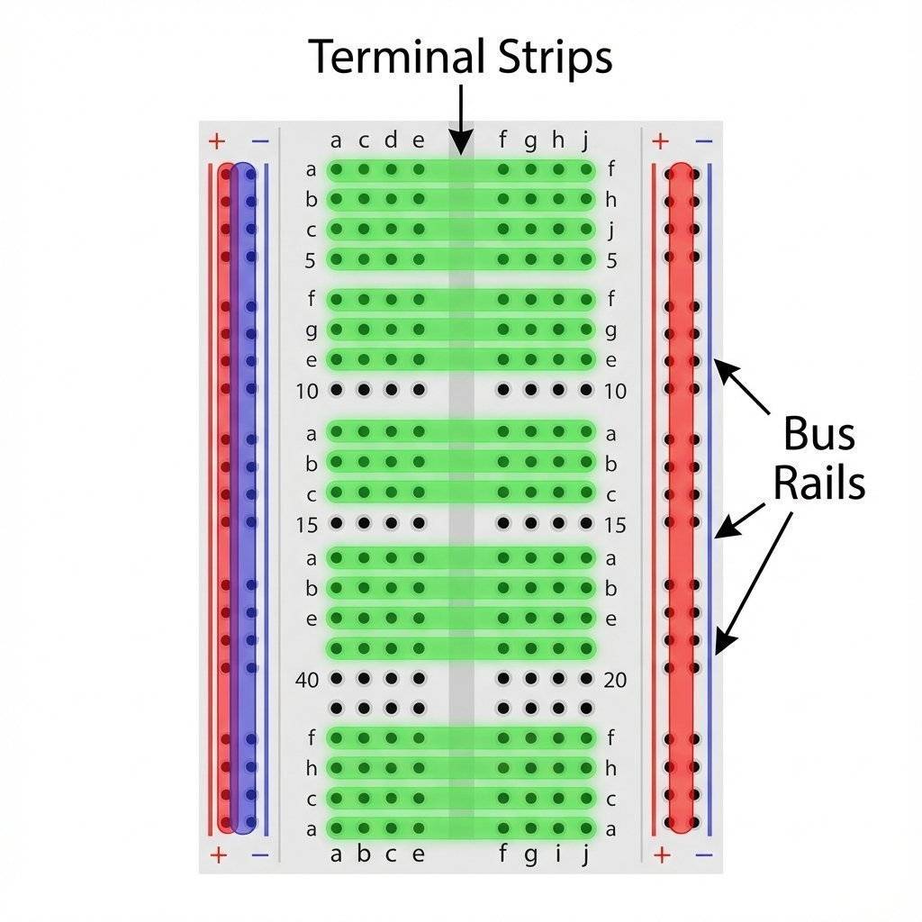
This is the main middle section where your chips, resistors, and LEDs live.
1. Holes a, b, c, d, e are all connected together.f, g, h, i, j are all connected together.1a is connected to 1e, but it is NOT connected to 1f. This gap is exactly the width of a microchip (IC).These are the long strips running down the sides, usually marked with Red (+) and Blue (-) lines.
[!WARNING] Trap for Young Players: On some very long breadboards, the power rails are split in the middle. If your circuit works on the top half but not the bottom, check if the red/blue lines are broken in the center. You might need to add a small jumper wire to bridge the gap.
It sounds ridiculous. Is it made of bread? No, but it used to be. In the 1920s and 30s, before plastic existed, engineers would literally steal their mother’s wooden bread cutting board. They would hammer copper nails into the wood and wrap wires around the nails to create connections. It was cheap, available, and non-conductive (wood). We kept the name, but swapped wood for plastic and nails for spring-clips. Next time you struggle with a wire, just be glad you aren’t using a hammer and nails.
Myth: “You need thick wires for breadboards.” Reality: Thick wires destroy the clips. Use 22 AWG solid core wire. Nothing else.
Myth: “I can run 110V wall power on a breadboard.” Reality: NEVER. The traces are thin and close together. will arc (jump) between rows, melt the plastic, and potentially start a fire. Keep it under .
Myth: “Ground is always the bottom rail.” Reality: It’s just a convention. You can make the top rail ground if you want. But stick to the convention (Blue = Ground) so you don’t confuse yourself later.
If I took away my multimeter, I would quit electronics. Trying to debug a circuit without one is like trying to paint a picture in a pitch-black room. You are just guessing.
Don’t be intimidated by the dial. It looks like the cockpit of a 747, but you only need 3 settings for 90% of your life.
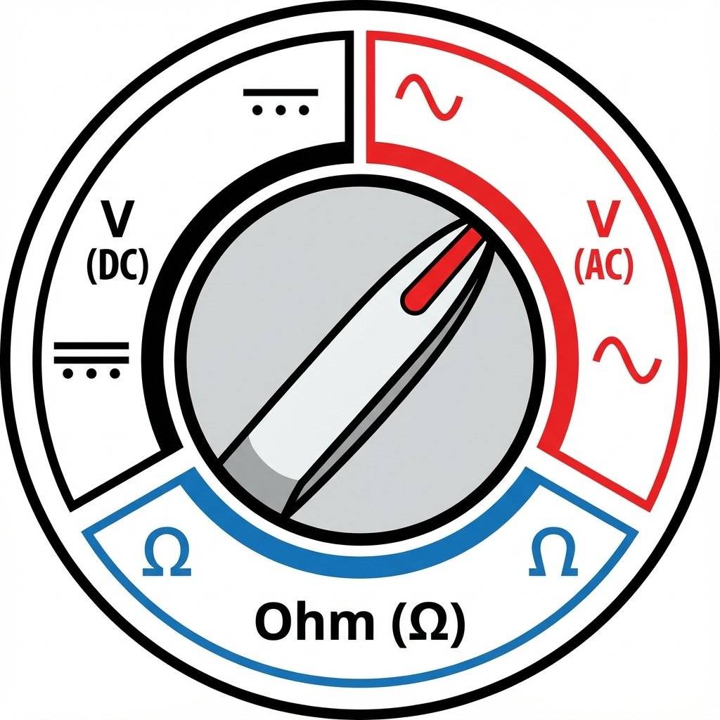
V with a straight line or dashed line ⎓.COM, Red probe covers V.$\Omega$.))) or a Diode symbol ->|.[!IMPORTANT] Safety Rule: Always plug the Black probe into COM (Common/Ground). Always plug the Red probe into the port marked . Avoid the port marked “10A” unless you know exactly what you are doing (it has no fuse!).
Enough talk. Let’s make photons.
The Mission: Light up a Red LED using a Battery.
The Parts:
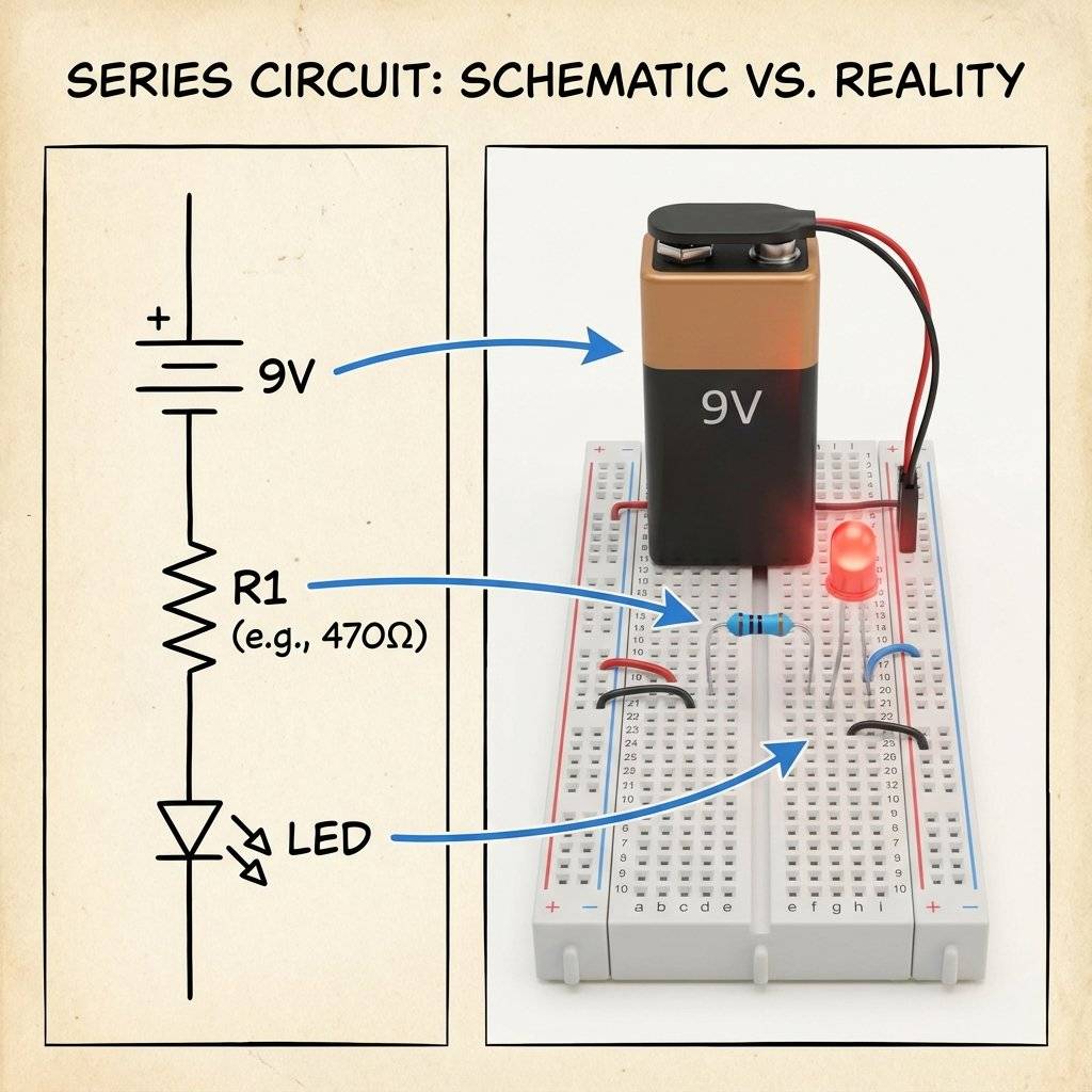
Connect the Red wire of your battery snap to the Red (+) Rail on the breadboard. Connect the Black wire to the Blue (-) Rail. Congratulations. You now have live power rails.
Pick up the LED. Look closer. One leg is longer than the other.
10e and Short Leg in 11e.We need to protect the LED from the fierce 9V pressure.
Plug one leg of the Resistor into 10a (same row as the LED Long Leg).
Plug the other leg into a different empty row, say 5a.
Current can now flow from 5a -> Resistor -> 10a -> 10e -> LED.
Now we connect the plumbing to the tanks.
5b (The start of the resistor).11a (The end of the LED).Check your wiring. Red Rail -> Wire -> Resistor -> LED (+) -> LED (-) -> Wire -> Blue Rail. Snap the battery in.
It Glows!
If it doesn’t:
You built it. But how do you know what’s happening? Let’s prove Ohm’s Law with the meter.
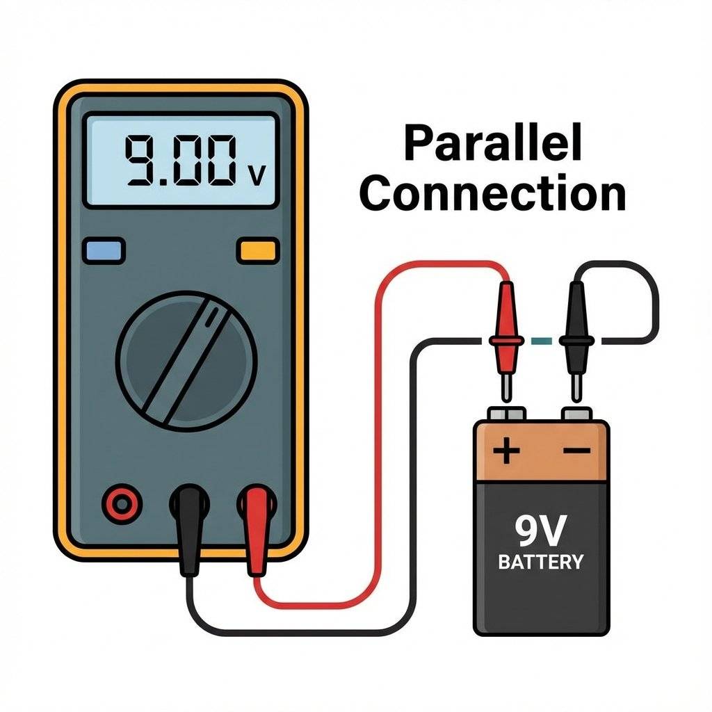
Turn your meter to 20V DC (or Auto DC). Touch the Black probe to the Blue Rail (Ground). Touch the Red probe to:
Warning: To measure current, we must become the wire.
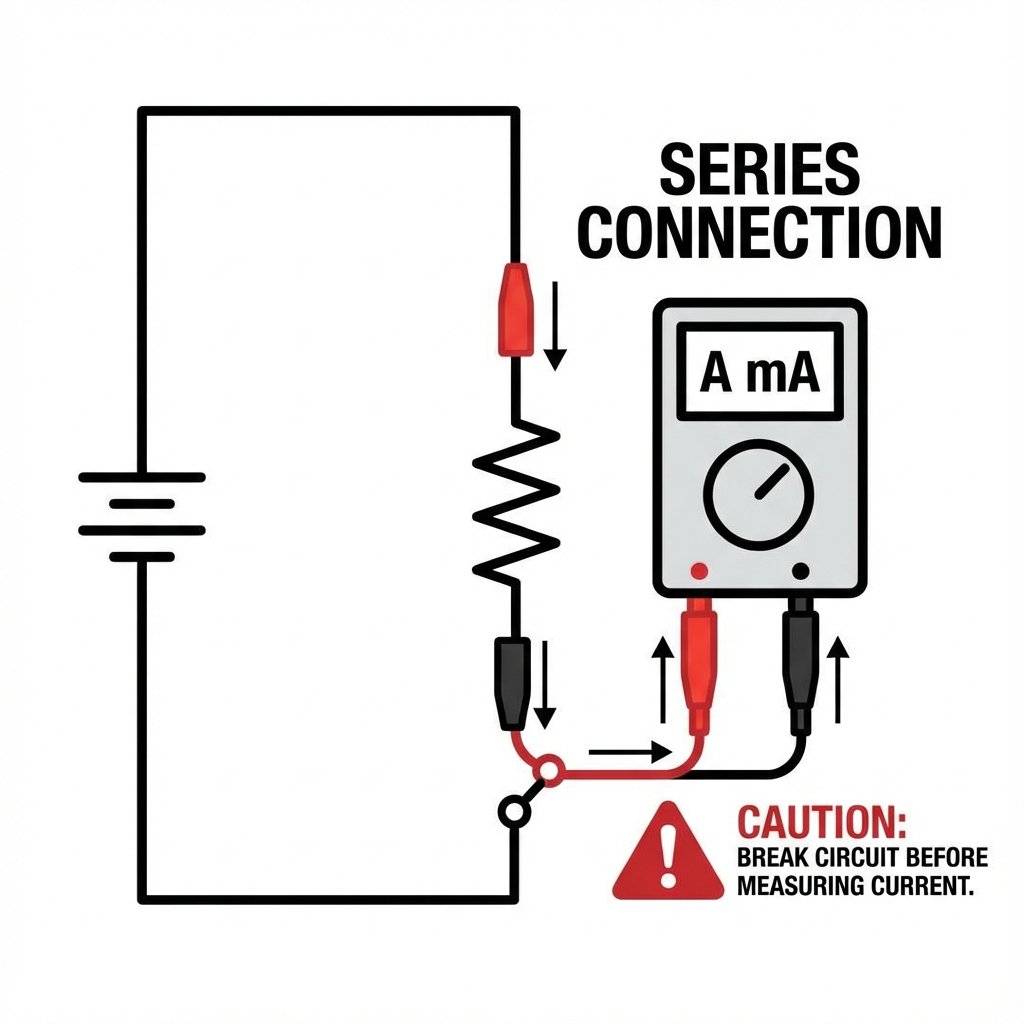
[!IMPORTANT] Always move the probe back to the “V” port immediately after measuring current. If you try to measure Voltage while the probe is in the “Amps” port, you will short-circuit your battery and blow the fuse in your meter.
You might have noticed something important. Some components care about which way you plug them in. Some don’t.
When things fail (and they will), don’t get mad. Go through the checklist.
The Open Circuit: Did a wire pop out? Breadboard clips are sometimes loose. Wiggle them.
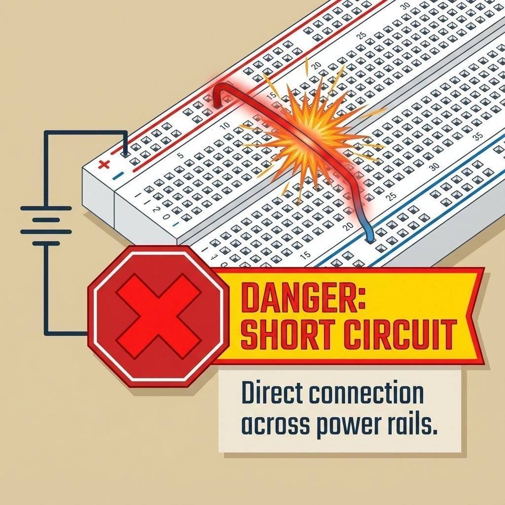
The Short Circuit: Did the two legs of the LED touch each other? That creates a path of zero resistance.
How do I know that resistor is ? Look at the colored bands.
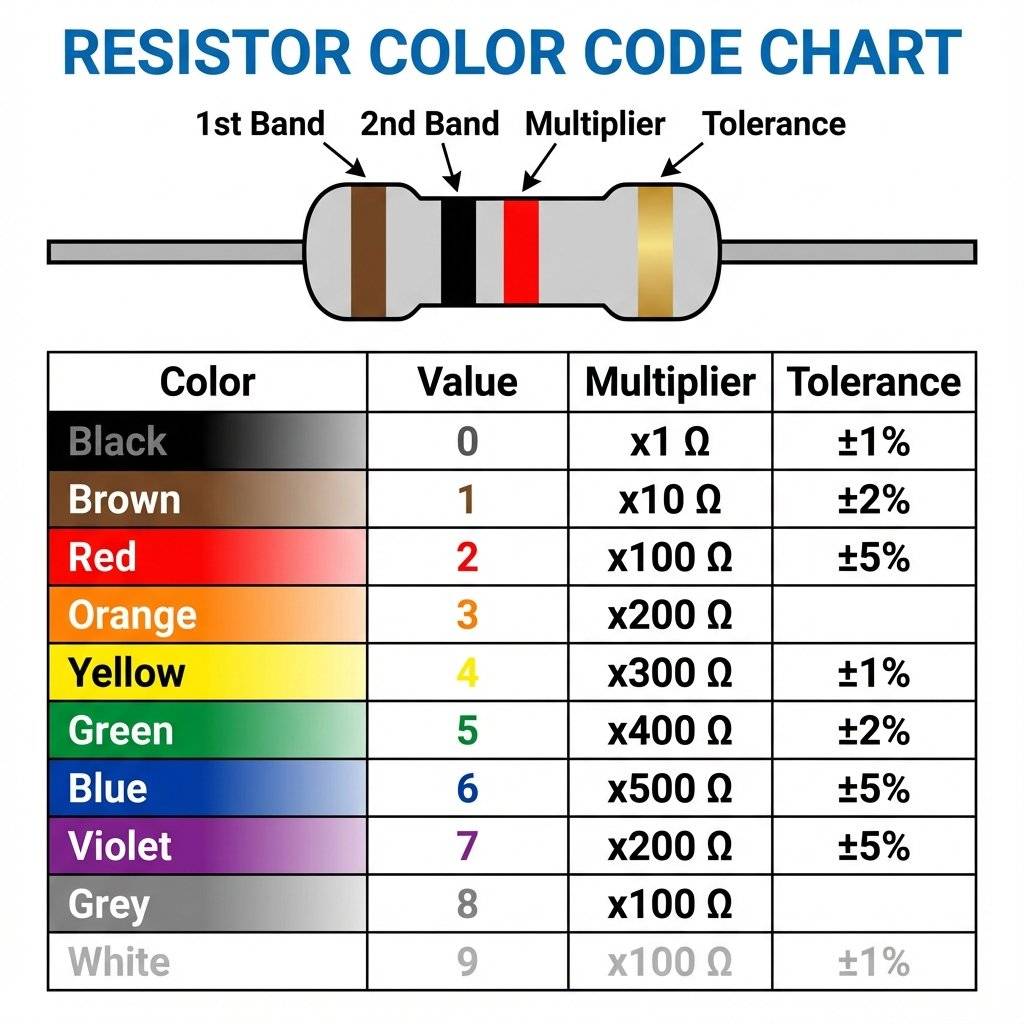
We will have a full guide on this later, but for now, just trust the bag labels or use your multimeter’s “” mode to check them.
Even with , safety matters.
We threw a lot of terms at you today. Here is your cheat sheet.
What actually happens when you push a wire in? Inside the plastic housing, there are metal clips made of phosphor bronze or nickel silver. These clips are shaped like a “U”. When you push the wire in, the “U” expands and grips the wire tight. This creates a gas-tight seal that prevents corrosion. However, these clips have limits.
Sometimes, it’s not fully broken, but it’s weird.
The LED turns on, but flickers when you move the board.
The LED is on, but it’s barely visible.
It flashes once brightly, then dies.
You may have seen people lick 9V batteries to test them. Do not do this. While not deadly, it sends current through your tongue (which is wet and conductive). It tastes metallic and hurts. Use your multimeter. That’s what you bought it for. Set it to “20V DC”.
You don’t need a $500 Fluke multimeter yet. Here is my tiered recommendation for beginners:
Tier 1 (The bare minimum):
One 830-point breadboard (The big one).
A cheap digital multimeter (The red ones for $10).
A jar of jumpers.
Tier 2 (Quality of Life):
A multimeter with “Auto-Ranging” (No need to select 2V/20V/200V).
Pre-formed jumper wires (They lie flat on the board, very neat).
Hemostats (precision tweezers) for placing components.
Tier 3 (The Lab):
Bench power supply (Dial in any voltage).
Oscilloscope (Visualizing voltage over time - we will get there).
Take a moment. Look at that LED glowing on your desk. It seems small. It seems trivial. But you built it. You took a source of chemical energy, routed it through metal conductors, throttled it with a carbon resistor, and converted it into photons using a semiconductor. That is not trivial. That is alchemy. You are no longer just a consumer of technology. You are a creator.
Now that we can build circuits, we need to control them. Tomorrow, we introduce the Transistor. The tiny switch that changed the world. We will learn how to use a small electrical signal to control a massive one, paving the way for logic and computers.
Rest up. Your hands are now hardware-certified.
Q: My breadboard feels stiff. Is that normal? A: Yes, brand new breadboards have tight clips. Pushing wires in takes force. It gets easier with time. Use pliers (gently) if your fingers hurt.
Q: Can I damage the LED? A: Yes. If you forget the resistor, the full 9V will hit it. It will flash bright orange, maybe make a pop sound, and let out the “Magic Smoke”. Once the magic smoke escapes, the component never works again.
Q: Does it matter which way the resistor goes? A: No! Resistors are non-polarized. They work both ways. Like a water pipe, flow is restricted regardless of direction.
Q: My multimeter reads “-9V”. Negative? A: You just have the probes swapped (Red on minus, Black on plus). The physics is fine, the meter is just telling you the direction is opposite to what it expected.
Q: What is a “Cold Solder Joint”? A: We are using breadboards, so soldering doesn’t apply yet! But it means a bad connection. On a breadboard, a “bad contact” is the equivalent.
Q: Can I use a 1.5V AA battery instead? A: Not directly for a standard LED. Most LEDs need at least 2V (Red) or 3V (Blue/White) to “turn on” (Forward Voltage). A single AA battery doesn’t have enough pressure to open the gate. You would need two AAs in series (3V).
Q: Why don’t I get a shock touching the battery? A: As we learned yesterday, your skin resistance is too high! isn’t enough pressure to push dangerous current through you. But don’t touch it to your tongue (low resistance).
Q: My circuit works, but the resistor is hot. Why? A: You might be using too low of a resistance, or your battery voltage is too high. Power (Watts) = (Voltage Drop * Voltage Drop) / Resistance. If the resistor can’t handle the heat (usually rated for 1/4 Watt), it burns up.
Q: Can I plug multiple wires into the same hole? A: No! The clips are designed for one wire. Jamming two in will permanently stretch the spring, ruining the contact. Use the adjacent hole in the same row instead.

Stop burning out your LEDs. Master electrical resistance, Ohm's Law calculations, and build your first protected circuit in Day 3 of our Electronics series.
Read More →
Understand electrical current like a pro. From drift velocity to safety, master the flow of electrons in Day 2 of our Analog Electronics series.
Read More →
Demystify voltage once and for all. Explore the physics, history, and practical measurement of electrical potential in this deep-dive guide for analog electronics beginners.
Read More →