The Great Restrictor: Mastering Resistance & Ohm's Law
Stop burning out your LEDs. Master electrical resistance, Ohm's Law calculations, and build your first protected circuit in Day 3 of our Electronics series.
Read More →
* SYSTEM.NOTICE: Affiliate links support continued laboratory research.
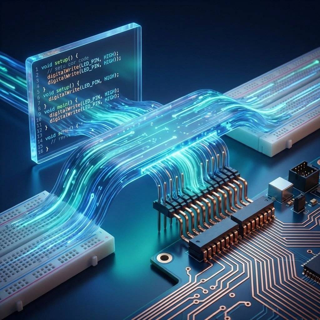
Welcome to the fourth stage of our hardware journey. If you’ve been following along, you’ve moved from basic circuits to understanding how atoms are probed and debugged. But now, we reach the most critical bridge of all: the moment where your code physically reaches out and touches the world.
As a software developer, you are used to APIs. You call a function, you pass a parameter, and you receive a response. You deal with abstractions—classes, objects, and interfaces. But in the world of microcontrollers, your API consists of physical, gold-plated silver traces called GPIO (General Purpose Input/Output) pins.
These pins are the “Ports” of your silicon server. They are the registers that let you move energy as easily as you move data. Today, we are going to demystify these pins. We are going to stop treating them like black boxes and start seeing them as the high-speed, programmable interfaces that they truly are.
We are moving from pixels to pins. Let’s speak the language of silicon.
Think of a GPIO pin as a single-bit database field that you can both READ and WRITE, but with one major difference: the “Value” is a physical voltage.
In your code, you might write digitalWrite(13, HIGH). To the microcontroller, this is an instruction to engage a physical MOSFET (transistor) and connect Pin 13 to the internal 5V or 3.3V rail. You aren’t just changing a memory address; you are physically shifting the energy state of a piece of copper.
This is the “Physical API.” Just as you wouldn’t send a JSON object to a REST endpoint that expects a protobuf, you shouldn’t send 12V to a 3.3V GPIO pin. Understanding the “Type System” of pins is the first step to becoming a hardware-proficient developer.
In software, a variable is usually just a place in memory. But a GPIO pin has a State Machine behind it. You must explicitly tell the silicon which way the data (electrons) should flow.
When you set a pin to OUTPUT, the microcontroller acts as a Source. It provides the energy. This is how you blink an LED, drive a motor, or send signals to a display.
storage.put("key", "value") or socket.send(data).When you set a pin to INPUT, the microcontroller acts as a Sensor. It stops providing energy and instead “listens” for a voltage level. The pin becomes high-impedance, meaning it draws almost no current.
storage.get("key") or request.body.
As developers, we are comfortable with types. GPIO pins also have types, but they are defined by how the silicon processes the incoming wave.
A digital signal is binary. It is either HIGH or LOW. In a 5V system, HIGH is 5V and LOW is 0V. There is no middle ground.
if (digitalRead(PUSH_BUTTON) == HIGH)
The world isn’t binary. Temperatures, light levels, and audio waves are continuous. To handle this, we use ADC (Analog-to-Digital Converter) pins. These pins “sample” the voltage and convert it into a number.
int sensorValue = analogRead(A0);float with a limited precision.
This is where software developers often get tripped up. In code, a boolean is either true or false. It can’t be “neither.” But in hardware, if a pin is set to INPUT and nothing is connected to it, it is Floating.
A floating pin is like an uninitialized pointer. It will pick up random electromagnetic noise from the air and pulse between HIGH and LOW millions of times per second.
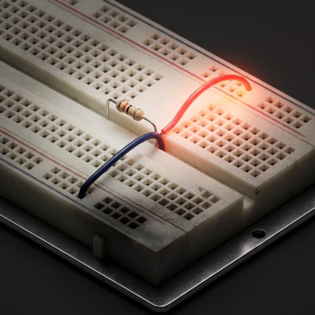
We use a high-value resistor (usually ) to “pull” the pin to a known state when nothing else is happening.
HIGH.LOW.Modern microcontrollers like the ESP32 and Arduino have Internal Pull-up Resistors that you can enable in one line of code:
pinMode(BUTTON_PIN, INPUT_PULLUP);
This is the hardware equivalent of a default parameter. It ensures your variable has a sane value before you start processing it.
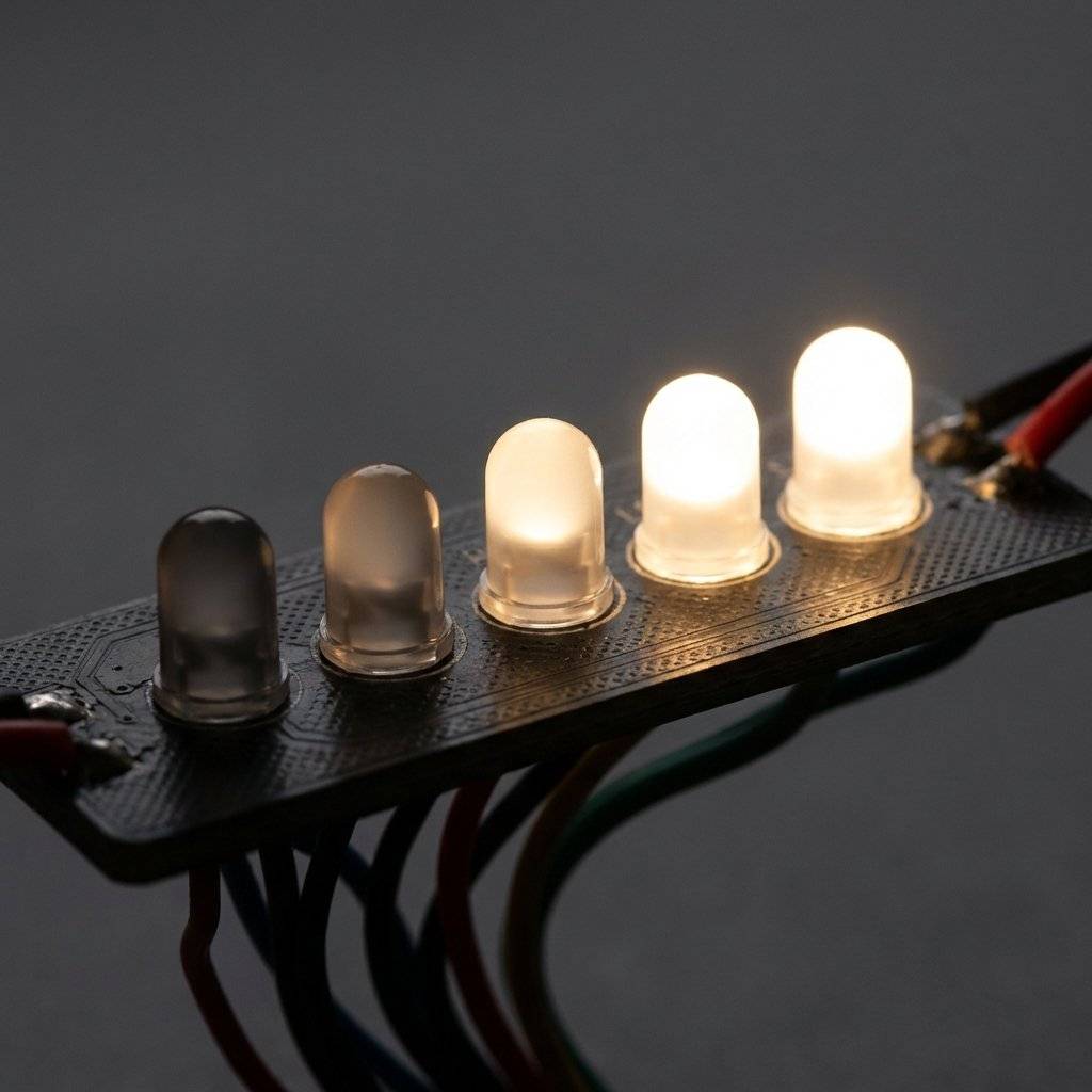
What if you want to dim an LED? Digital pins can only be ON or OFF. You could use an Analog Output (DAC), but those are expensive and rare on beginner chips. Instead, we use PWM (Pulse Width Modulation).
PWM is the “Hardware Loop.” We switch the pin between HIGH and LOW so fast (thousands of times per second) that the physical world (or our eyes) cannot keep up. We vary the Duty Cycle—the percentage of time the pin stays HIGH.
As a dev, think of PWM as a high-frequency while(true) loop that adjusts the average energy output without ever leaving the digital domain.

One of the most profound concepts in GPIO that software developers often miss is the Output Driver Configuration. When you write code, you see a binary state. But behind the scenes, the physical architecture determines how that state is achieved.
Most microcontroller pins operate in Push-Pull mode. Inside the silicon, there are two MOSFETs (transistors) acting as gates.
Some pins (especially on communication buses like I2C) operate in Open-Drain mode. In this mode, the pin can only pull the signal to LOW (GND). It cannot push it to HIGH. To get a HIGH state, we rely on an external pull-up resistor.

We previously discussed Duty Cycle (the “brightness” control), but as a developer, you need to understand the Frequency.
If your Duty Cycle is 50%, the pin is ON half the time. But how often does that cycle repeat?
Have you ever seen a video of a digital dashboard where the numbers seem to be vibrating or flashing? That is a aliasing issue between the PWM frequency of the display and the frame rate of the camera.
In high-level programming, we avoid “Polling” whenever possible. We don’t want a while(true) loop checking if a button is pressed; we want an Event Listener. In hardware, this is called an Interrupt (ISR).
An Interrupt physically “halts” the CPU the moment a pin changes state.
void setup() {
  pinMode(BUTTON_PIN, INPUT_PULLUP);
  // Attach an 'Event Listener' to the pin
  attachInterrupt(digitalPinToInterrupt(BUTTON_PIN), handleButtonPress, FALLING);
}

// This function runs INSTANTLY when the button hits GND
void handleButtonPress() {
  systemActive = !systemActive;
}Serial.print() or delay() inside an interrupt. Think of it like a “Strict Mode” callback in a high-performance rendering engine. If you block the ISR, you block the entire universe of your microcontroller.When you click a button in a web app, the browser handles the click event. But in hardware, a button is two pieces of metal hitting each other. They don’t just “connect”; they bounce.
To a microcontroller running at 16MHz, a single finger press looks like 50 separate clicks. If you don’t “debounce,” your counter++ code will go from 0 to 42 in a split second.
We can fix this in code by ignoring follow-up signals for a short time (e.g., 50ms).
void loop() {
  if (digitalRead(BUTTON_PIN) == LOW) {
    // We detected a press!
    count++;
    // Now we wait for the physical vibration to stop
    delay(50);
    // Wait for the user to let go
    while(digitalRead(BUTTON_PIN) == LOW);
  }
}
This is exactly like “Throttling” or “Debouncing” a scroll event in JavaScript. The physical world has a “latency” that our high-speed silicon needs to account for.
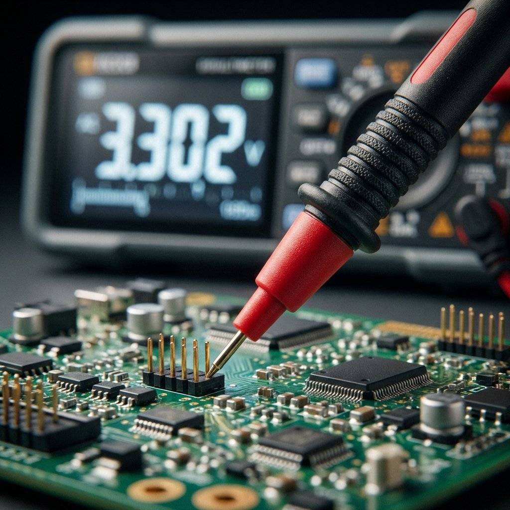
Behind every GPIO pin is a complex set of buffers and protection circuits. When you’re measuring a pin with a multimeter, you’re interacting with these structures.
A GPIO pin is essentially a pair of MOSFETs in a “Push-Pull” configuration. One MOSFET pulls to VCC, the other pulls to GND. When you’re in INPUT mode, both are “Off,” and the signal passes through a Schmitt Trigger (the digital logic gate that cleans up the signal).
If you draw too much current from a pin (usually more than 20mA), the internal traces in the silicon will physically melt. There is no software stack trace for this. It’s a permanent “Hardware Null Pointer.”
Never trust your code alone. Use your multimeter to verify the state of your pins.
If your code says HIGH but the meter says 0.2V, you have a short circuit or a software bug where the pin wasn’t initialized correctly. This is the hardware version of console.log(pin_state).
As a software developer, your worst nightmare is a segmentation fault. In hardware, it’s the smell of ozone.
Every GPIO pin has a Max Source Current (usually 20mA-40mA). If you try to power a 100mA motor directly from a pin, you aren’t just getting an error message; you are physically burning out the microscopic copper traces inside the chip.
Just as we use libraries to protect our code from malicious input, we use Transistors or Optoisolators to protect our pins from high-power loads.
We’ve talked about the multimeter, but when your GPIO signals are moving at megahertz speeds, the multimeter is too slow. It will only show you an “Average” voltage.
A Logic Analyzer is like a multi-channel stdout logger. It plugs into your USB and captures the exact timing of every 0 and 1 on your pins.
! to a ). In hardware, without the analyzer, you’d be guessing for days.Your code lives in a perfect, hermetically sealed world of logic. Hardware lives in a world of static electricity and radio interference.
A tiny spark from your finger—one you can’t even feel—can carry 10,000V. This is enough to “punch a hole” through the microscopic gates of a GPIO pin.
A long wire acting as an antenna can pick up signals from a nearby cell phone or a refrigerator motor.
As a developer, you use Docker to simulate production environments. In hardware, we use Wokwi or Tinkercad. These are “Digital Twins” of the physical chips.
Imagine this: your Arduino is powered by USB, and your motor is powered by a 9V battery. You connect the GPIO pin to the motor driver. The motor doesn’t move.
Response channel configured. The request goes out, but nothing ever comes back.Let’s expand our vocabulary so you can talk to electrical engineers without sounding like a “Web Dev.”
Let’s refine our nightlight project with Interrupts for responsiveness and Hysteresis to prevent flickering.
/*
 * From APIs to GPIO: The Adaptive Nightlight
 * Part 4 of The Software Developer's Hardware Journey
 */

#include <Arduino.h>

const int SENSOR_PIN = A0;   // Analog Input (Light Sensor)
const int LED_PIN = 9;       // PWM Output (Dimmable LED)
const int BUTTON_PIN = 2;    // Digital Input (Toggle Button)

volatile bool systemActive = true;
int lightThreshold = 400;
int hysteresis = 50;

void handleButton() {
  static unsigned long lastTime = 0;
  unsigned long currentTime = millis();

  // Software Debounce inside the ISR
  if (currentTime - lastTime > 250) {
    systemActive = !systemActive;
    lastTime = currentTime;
  }
}

void setup() {
  Serial.begin(115200);
  pinMode(LED_PIN, OUTPUT);
  pinMode(BUTTON_PIN, INPUT_PULLUP);

  // Attach the Hardware Event Listener
  attachInterrupt(digitalPinToInterrupt(BUTTON_PIN), handleButton, FALLING);
  Serial.println("System Ready: Adaptive Nightlight v2.0");
}

void loop() {
  if (systemActive) {
    int val = analogRead(SENSOR_PIN);

    // Hysteresis Logic: Software filter for stable state transitions
    static bool lightIsOn = false;
    if (!lightIsOn && val < (lightThreshold - hysteresis)) {
      lightIsOn = true;
    } else if (lightIsOn && val > (lightThreshold + hysteresis)) {
      lightIsOn = false;
    }

    if (lightIsOn) {
      // Breathing effect using PWM math
      float pulse = (exp(sin(millis() / 2000.0 * PI)) - 0.36787944) * 108.0;
      analogWrite(LED_PIN, (int)pulse);
    } else {
      analogWrite(LED_PIN, 0);
    }
  } else {
    digitalWrite(LED_PIN, LOW);
  }
}Look at the code above. You are managing State (systemActive), Thresholds (abs(lightValue - lastLightValue) > 10), and API Mapping (map(...)). This is the same logic you use in a React dashboard or a backend service. The only difference is that your “User Interface” is a literal photon-emitting diode.
| Term | Programmer Translation | Why You Care |
|---|---|---|
| Logic HIGH | true (Boolean) | Usually 3.3V or 5V. |
| Logic LOW | false (Boolean) | Ground (0V). |
| Hi-Z | null / undefined | The pin is effectively disconnected. |
| Pull-up | Default Value | Prevents random “Floating” values. |
| Sourcing | PROVIDE from Output | Current flowing OUT of the pin from VCC. |
| ADC | parseFloat(voltage) | Converting physical waves to numbers. |
| PWM | throttle() | Simulating analog intensity with time. |
By understanding GPIO, you have unlocked the final layer of the stack. You are no longer just a “Software” developer; you are a System Engineer. You understand how logic becomes energy, and how energy becomes data.
The pins on your microcontroller are not just connectors; they are the entry points to the physical world. They are the APIs of reality.
In the next installment of our journey, we will step beyond single pins and explore The Bus: Talking to Sensors with I2C and SPI. We’ll learn how to have high-level “Conversations” with intelligent components.
Until then, grab your multimeter, blink some LEDs, and remember: The Code doesn’t stop at the screen. It’s just getting started.

Q: Why does my code work with Serial.print() but fail without it?
A: This is a classic “Timing Bug.” Serial.print() adds a small delay. In hardware, things happen so fast that sometimes your code “outruns” the physical components. You might need to add a few delayMicroseconds() to let the electricity catch up.
Q: Can I use GPIO pins to power a Raspberry Pi? A: Absolutely NOT. GPIO pins are for signals, not for power delivery. Trying to power a computer through a signal pin is a guaranteed way to see a “Blue Screen of Smoke.”
Q: Is “Low” always 0V? A: In an ideal world, yes. In reality, anything below 0.8V is usually “Low.” If your ground wires are long or messy, your “Low” might rise to 1.5V, causing random logic failures. Always keep your Ground connections clean and solid.
Q: How do I know which pin is which? A: Search for “[Your Board Name] Pinout.” Always keep this image open in a separate tab while working. Guessing a pin orientation is the #1 cause of hardware failure.

Stop burning out your LEDs. Master electrical resistance, Ohm's Law calculations, and build your first protected circuit in Day 3 of our Electronics series.
Read More →
Understand electrical current like a pro. From drift velocity to safety, master the flow of electrons in Day 2 of our Analog Electronics series.
Read More →
Demystify voltage once and for all. Explore the physics, history, and practical measurement of electrical potential in this deep-dive guide for analog electronics beginners.
Read More →