The Great Restrictor: Mastering Resistance & Ohm's Law
Stop burning out your LEDs. Master electrical resistance, Ohm's Law calculations, and build your first protected circuit in Day 3 of our Electronics series.
Read More →
* SYSTEM.NOTICE: Affiliate links support continued laboratory research.
Welcome to Day 4.
Look at the device you are reading this on. Phone? Laptop? Desktop? Inside that device are billions—yes, billions—of microscopic switches turning on and off billions of times per second. Those switches are not mechanical. They have no moving parts. They never wear out. They are Transistors.
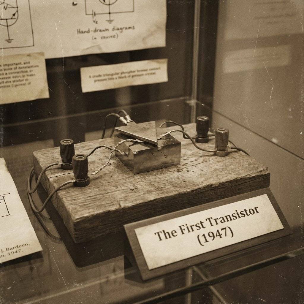
In 1947, a transistor was the size of your hand. Today, we fit 50 billion of them on a chip the size of your fingernail. It is, without hyperbole, the most important invention in human history.
Today, you are going to hold one in your hand. And you are going to make it do your bidding.
Set aside the physics degree. Forget “Quantum Tunneling” and “Depletion Regions” for a second. A Transistor is a Digital Valve.
Think of a water tap.
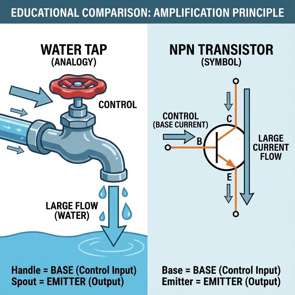
A transistor is identical.
We are using the 2N2222 (or BC547). This is an NPN transistor. It looks like a tiny black D-shape with three legs.
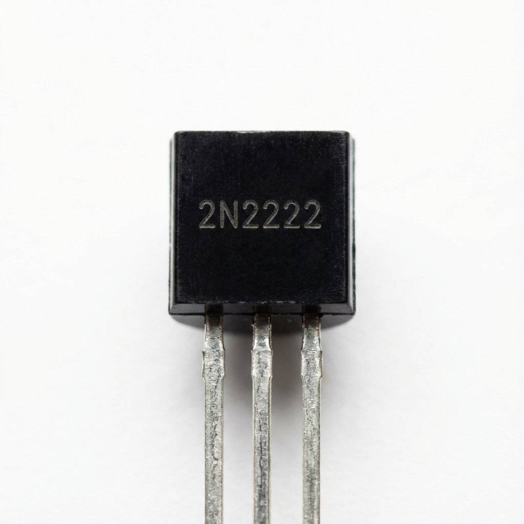
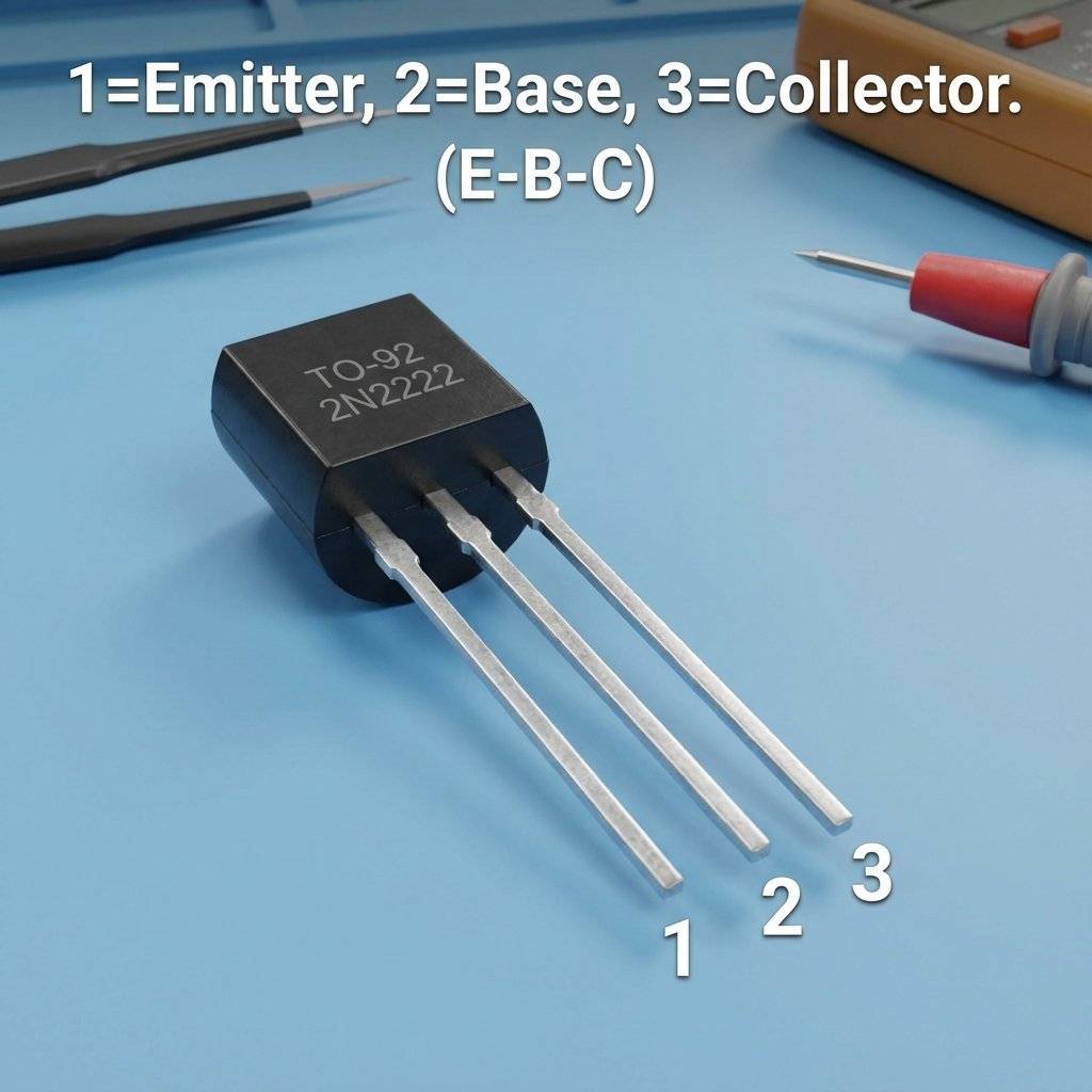
Holding the flat side facing you, legs pointing down:
(Note: If you are using a BC547, the pins might be reversed C-B-E. Always check the datasheet! But for 2N2222, it’s usually E-B-C).
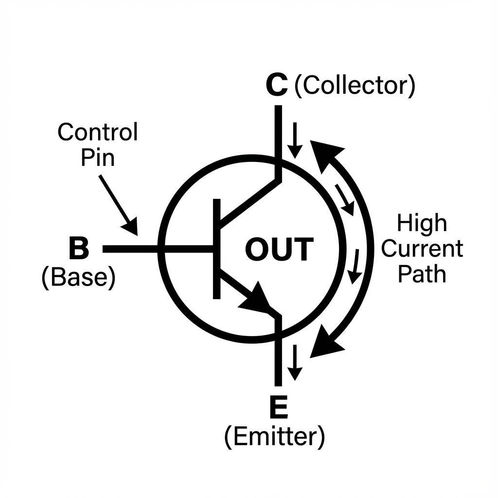
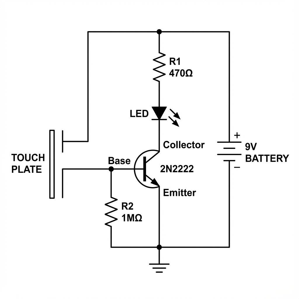
On a schematic, it looks like this. The arrow points OUT.
We are going to build a circuit where the “Switch” is literally your skin. Your body has resistance, but it conducts enough electricity to trigger a transistor.
The Goal: Touch a wire, LED turns on. Let go, LED turns off.
The Parts:
Put the transistor in three separate rows. Flat side facing you.
Connect a jumper from Row 10 (Emitter) directly to the Blue (-) Rail.
We put the LED before the transistor (on the Collector side).
Connect Row 12 (Collector) to the Cathode (Short leg) of the LED.
Connect the Anode (Long leg) of the LED to a Resistor.
Connect the other side of the Resistor to the Red (+) Rail.
Path check: Power -> Resistor -> LED -> Transistor Collector -> Transistor Emitter -> Ground.
Now, the control. Plug a long jumper wire into Row 11 (Base). Leave the other end dangling in the air. Plug another jumper wire into the Red (+) Rail. Leave the end dangling.
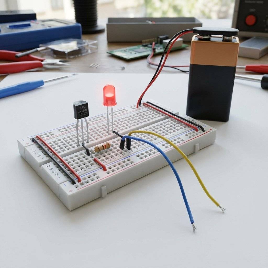
Plug in the battery (). Nothing happens. The valve is closed. Now, grab the metal tip of the dangling “Base” wire with one finger. Grab the metal tip of the dangling “Positive” wire with the other finger.
The LED lights up.
went through your body, through your fingers, into the Base of the transistor. The current was tiny (). You couldn’t feel it. But the transistor felt it. It amplified that tiny signal times, opening the floodgates for the LED.
You just witnessed Gain. Every transistor has a rating called Beta (or hFE). For a 2N2222, Beta is usually ~100. This means: 1 electron into the Base allows 100 electrons to flow through the Collector. This is how your phone works. A tiny, weak Wi-Fi signal hits an antenna. It goes into a transistor. The transistor uses battery power to copy that signal and make it strong enough to drive a speaker.
We used the transistor as a Switch (On/Off). But it is also an Amplifier. If you send a fluctuating signal (like music) into the Base, the transistor mimics that fluctuation on the other side, but with more power. This is “Class A” amplification. The downside? It gets hot. The transistor is effectively a variable resistor, burning off excess energy as heat to regulate the flow. We will build a simple Speaker Amplifier in Week 2, but for now, just understand that switching and amplifying are two sides of the same coin.
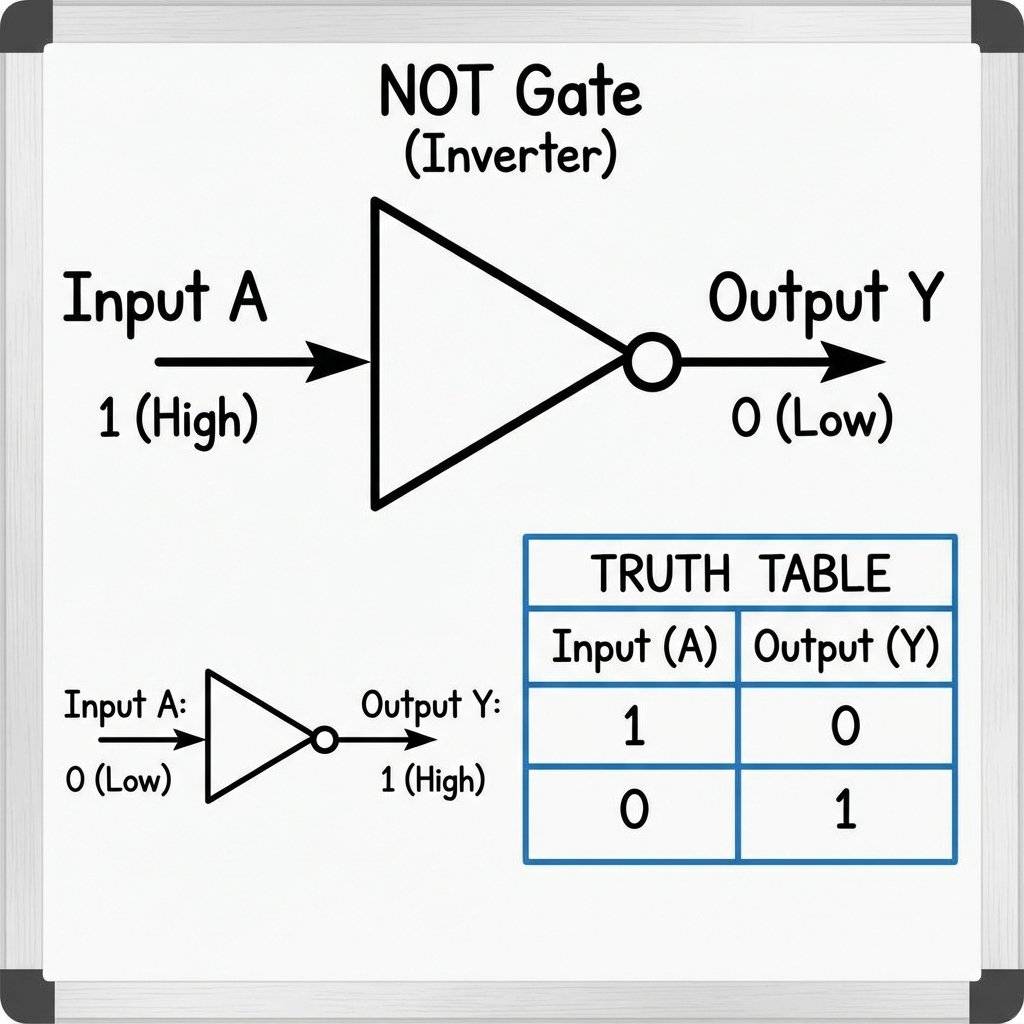
Computers think in 1s and 0s. How do we make a “0” from a “1”? We use a NOT Gate (Inverter).
Let’s modify our circuit.
Keep the Transistor Emitter connected to Ground.
Connect the LED Anode to +9V (with resistor).
Connect the LED Cathode to the Collector.
NEW: Add a connection from Collector to a “Output Wire”.
When you turn the transistor ON (High Input): The path to ground becomes effortless (short circuit). The voltage at the Collector drops to . The Output goes LOW.
When you turn the transistor OFF (Low Input): The path to ground is blocked. The voltage at the Collector floats up to . The Output goes HIGH.
You just built the fundamental building block of CPU logic.
Every component has a manual called a Datasheet. Let’s decode the 2N2222. Search for “2N2222 datasheet” and you will see a table.
What it means: The maximum pressure the valve can hold back.
In English: If you put more than across it, it breaks. Since we use , we are safe.
What it means: The maximum flow rate.
In English: It can handle . Our LED uses . We are super safe. If you tried to drive a motor, it would melt.
What it means: The amplification factor.
In English: If you feed into the Base, you get — at the Collector.
What it means: How much heat it can dump.
In English: If it gets too hot, it dies. Keep it cool.
What if your fingers are too dry? Or you want to detect a static charge from a balloon? One transistor amplifies ~100x. What if we feed the output of Transistor A into the input of Transistor B? Gain = 100 x 100 = 10,000x.
Transistor 1 (the pre-amp): Collector to . Emitter connects to the base of Transistor 2.
Transistor 2 (The Power-Amp): Collector to . Emitter to LED.
Base: Your touch input goes to Transistor 1 Base.
Now, you don’t even need to touch the wire. Just bringing your hand near it might trigger it due to the electromagnetic field of your body. You just built a proximity sensor.
Reality: No. They control energy. The power comes from the battery. The transistor just modulates it. It’s a valve, not a pump.
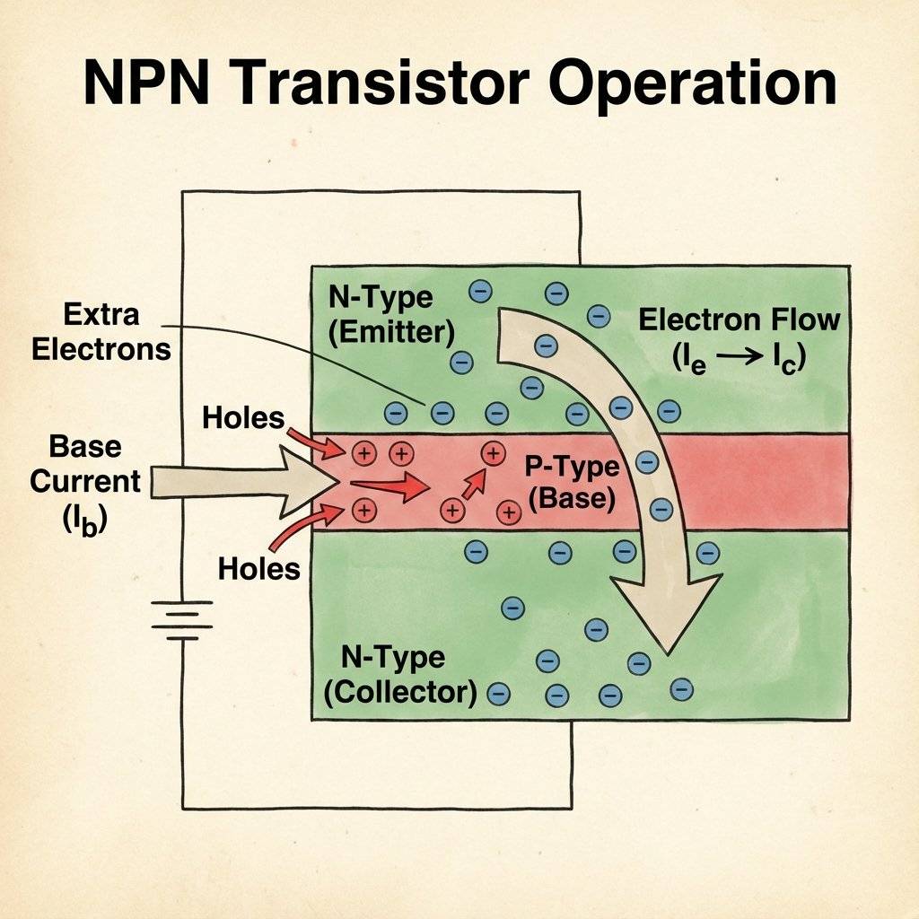
Reality: Pure silicon is an insulator! That’s why we call it a Semi-conductor. It only conducts when we inject impurities (Doping) and apply a voltage field.
Reality: NO. A MOSFET (Voltage controlled) is very different from a BJT (Current controlled). Mixing them up will result in a circuit that does absolutely nothing. Silicon is boring. It doesn’t conduct. To make it interesting, we dope it.
An NPN sandwich is a slice of P-type between two slices of N-type. Normally, electrons can’t jump across. But when we energize the middle P-layer (Base), it creates a bridge.
You might think, “I don’t use transistors.” You are wrong.
If all transistors vanished, civilization would collapse in 8 milliseconds.
We are using the TO-92 (The little plastic d-shape). But they come in all sizes.
It works on paper. But does it work on your desk?
Issue: LED stays lit even when you don’t touch the wires.
Diagnosis: Floating Base.
Fix: Add a “pull-down” resistor. Connect a high-value resistor ( or ) from the base to ground.
Issue: Touching the wires does nothing.
Diagnosis: Fingers are too dry (High resistance).
Fix: Lick your fingers (seriously) or hold the wires tighter. Or, use a Darlington Pair (Stacking two transistors) to increase sensitivity.
Issue: A flash of light, a smell of plastic, then death.
Diagnosis: No Base Resistor.
Fix: You connected the Base directly to . The P-N junction melted. Throw it away and use a resistor next time.
Issue: The transistor works, but burns your finger.
Diagnosis: Overload.
Fix: You are trying to drive something too big (like a motor) with a small TO-92.
Solution A: Use a bigger resistor on the base to limit current (Cooler, but dimmer LED).
Solution B: Upgrade to a “Power Transistor” like a TIP120 or a MOSFET.
Solution C: Add a heatsink. (Though gluing a penny to a TO-92 is mostly a joke).
Before transistors, we had Vacuum Tubes. They were the size of lightbulbs, hot, fragile, and consumed massive power. The first computer (ENIAC) had 18,000 tubes and filled a room. At Bell Labs in 1947, Shockley, Bardeen, and Brattain invented the point-contact transistor. It looked like a piece of trash. A paperclip pressing onto a germanium block. But it worked. They won the Nobel Prize. And they gave us the modern world.
Gordon Moore, a co-founder of Intel, noticed a trend in 1965. “The number of transistors on a chip doubles every two years.” He was right.
| Feature | BJT (2N2222) | MOSFET (IRLZ44N) |
|---|---|---|
| Control | Current (Base) | Voltage (Gate) |
| Switching Speed | Fast | Ultra Fast |
| Heat | Wastes power | Very Efficient |
| Usage | Small signals | Big Power |
| Symbol | Arrow on Emitter | Gap in line |
Working with these tiny three-legged beasts requires some finesse.
I want you to pause and look at your simple LED circuit. You touch the wire. The light turns on. You just controlled a flow of electrons using nothing but your presence. The component you just used—the 2N2222—costs $0.02. Yet, it is the same fundamental machine that calculates the trajectory of rockets, renders your video games, and processes the AI writing this very sentence. You have mastered the “Bit”. The “1” and the “0”. You are now speaking the language of computers.
Here is a puzzle for you. Can you wire a circuit so that when you touch the button ONCE, the LED stays ON forever? (Hint: You need to feed the output of the transistor back into its own Base). This is called a “Latch” or a “Thyristor” effect. Give it a try. If you figure it out, you just invented computer memory (SRAM).
We have resistors (Friction), Capacitors (Springs), and Transistors (Valves). Tomorrow, we learn about The Clock. How do computers minimize time? We will meet the 555 Timer, the heartbeat of electronics.
Q: Can I use a 2N3904 instead of 2N2222? A: Yes! They are almost identical for hobby circuits. Just check the pinout to be sure.
Q: Why do we need a resistor on the Base? A: To protect the transistor! The Base-Emitter path is basically a diode. If you connect it directly to , infinite current flows and the transistor explodes. Always use a resistor ( or ).
Q: My Touch Switch turns on when I just wave my hand near it! A: Congratulations, you built an antenna. Your body acts as a capacitor coupling mains hum from the walls into the sensitive base.
Q: What is a MOSFET? A: It’s a modern type of transistor. NPNs are controlled by Current. MOSFETs are controlled by Voltage. MOSFETs are what CPUs are made of because they are more efficient.
Q: Can I control a motor with this? A: Yes! But motors create “Flyback Voltage” when they stop spinning, which can kill the transistor. You need a “Flyback Diode” to protect it. We will cover this later.

Stop burning out your LEDs. Master electrical resistance, Ohm's Law calculations, and build your first protected circuit in Day 3 of our Electronics series.
Read More →
Understand electrical current like a pro. From drift velocity to safety, master the flow of electrons in Day 2 of our Analog Electronics series.
Read More →
Demystify voltage once and for all. Explore the physics, history, and practical measurement of electrical potential in this deep-dive guide for analog electronics beginners.
Read More →