The River vs The Lightning: Mastering Current Flow
Understand electrical current like a pro. From drift velocity to safety, master the flow of electrons in Day 2 of our Analog Electronics series.
Read More →
* SYSTEM.NOTICE: Affiliate links support continued laboratory research.
We are on Day 3 of our journey into the heart of electronics.
On Day 1, we learned that Voltage is the push. On Day 2, we learned that Current is the flow. Today, we meet the Restriction.
Resistance is the control. Without it, voltage would push infinite current, wires would melt, and components would explode in milliseconds. Resistance turns the chaotic flood of electrons into a manageable stream. It is the dam that harnesses the river.
In this guide, we won’t just memorize a formula. We are going to visualize the collision of atoms, derive the most famous equation in history, and finally, build a circuit that proves it all with a multimeter.

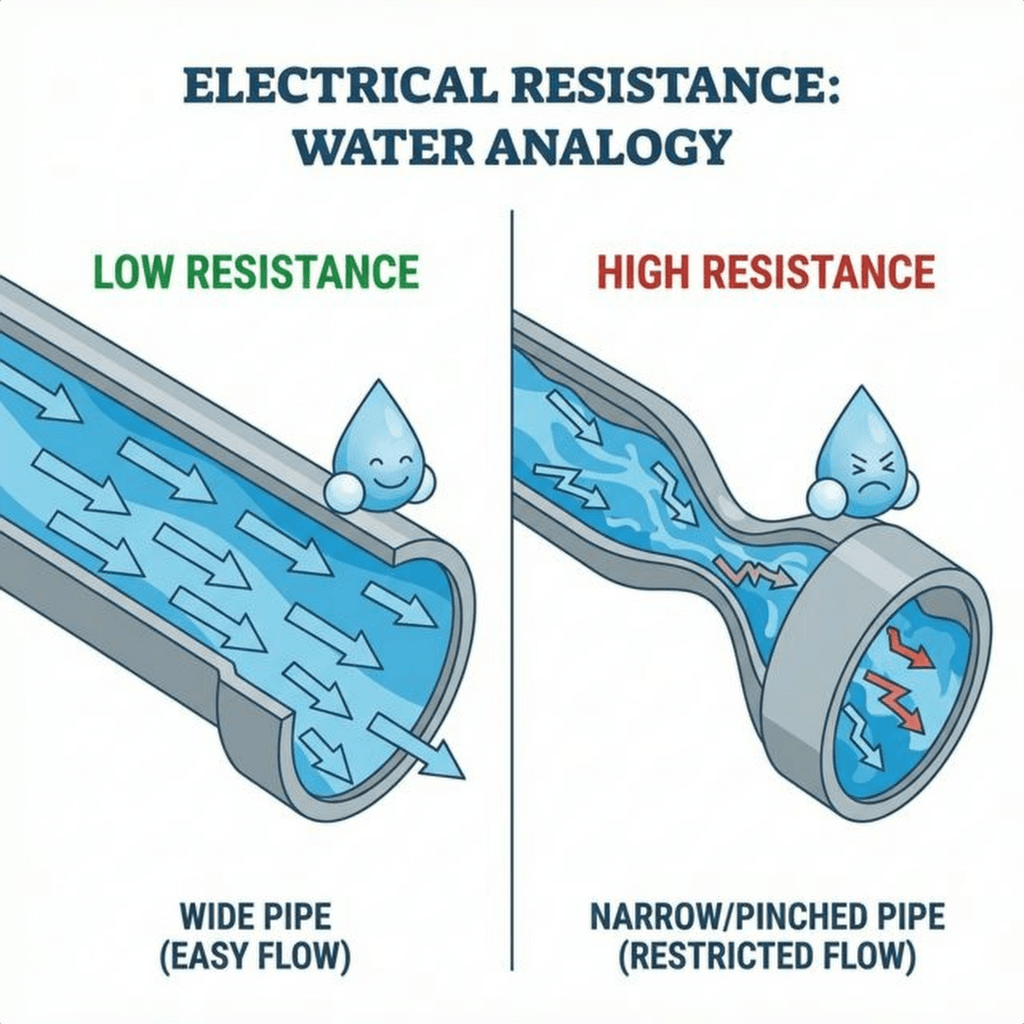
Imagine your garden hose again.
Now, imagine you step on the hose. You create a restriction. The pressure (Voltage) is still there, pushing hard against your foot. But the flow (Current) drops to a trickle.
That restriction is Resistance.
If you step harder (Higher Resistance), flow decreases. If you stick a huge rock inside a wide pipe (Resistor), the water has to squeeze around it, slowing down.
Why does resistance happen? Why isn’t every wire a superconductor?
Inside a copper wire, electrons are trying to drift under the influence of voltage. But the copper atoms themselves are vibrating (due to heat). As electrons rush forward, they crash into these vibrating atoms.
Bang. An electron hits an atom. It loses its kinetic energy, which causes the copper atom to vibrate even faster. Vibrating atoms = Heat.
This is why resistors get warm. They are literally converting electrical energy (electron motion) into thermal energy (atomic vibration) through billions of microscopic collisions every second.

In 1827, Georg Simon Ohm discovered a trend. He noticed that for most materials, if you double the voltage, you double the current. It was a perfect, linear relationship.
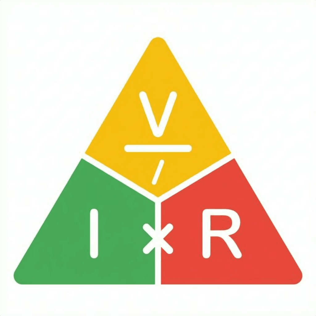
He wrote it down as:
This is Ohm’s Law. It is the of electronics.
You can rearrange this triangle to find any missing value:
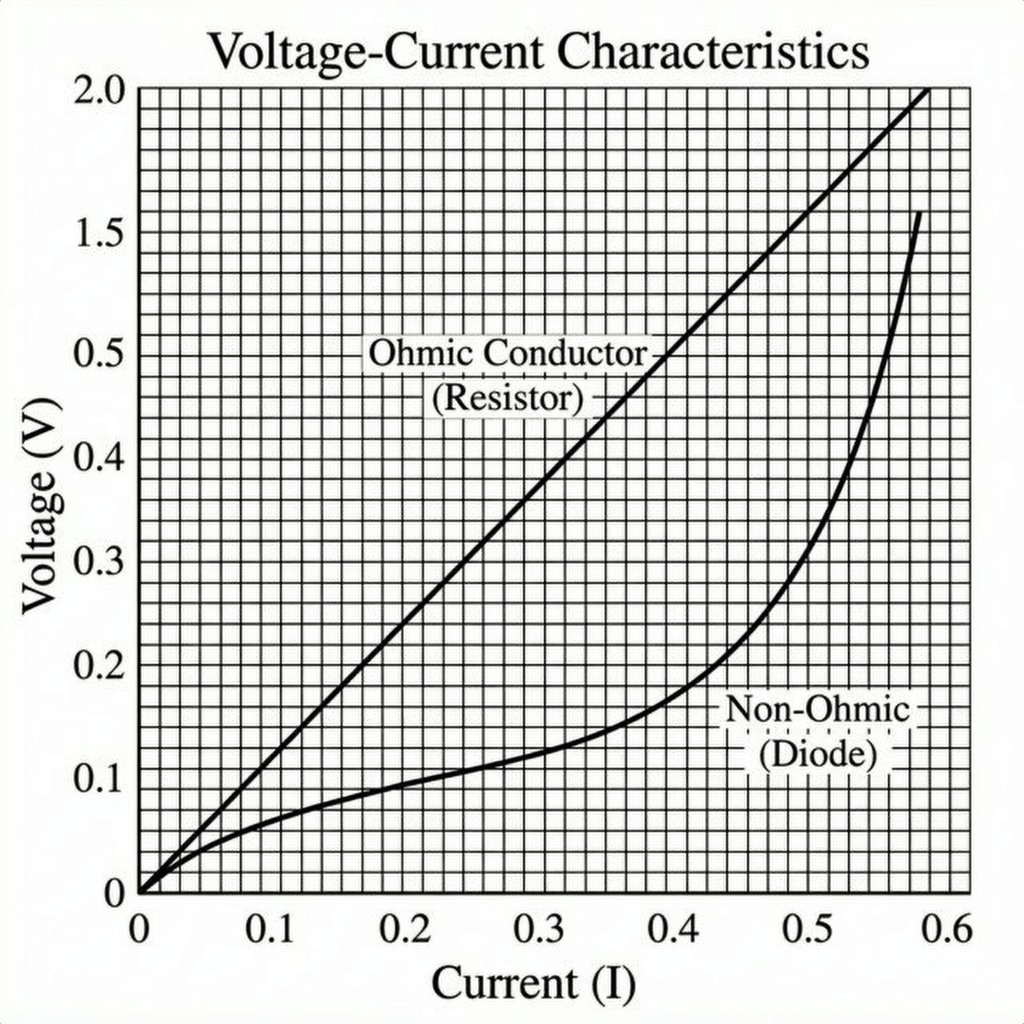
If you plot Voltage vs Current for a standard resistor, you get a straight line. The steeper the line, the higher the resistance. This is called an “Ohmic” device.
(Note: Not everything is Ohmic! An LED or Diode has a curved graph, which is why they are trickier to handle. We’ll get to that.)
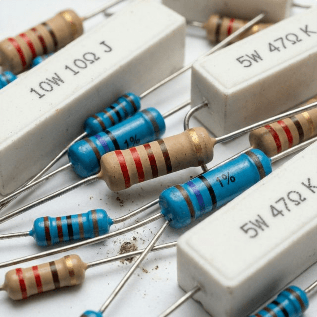
A Resistor is a component dedicated to adding a specific amount of resistance. They are made of carbon film, metal film, or wire wound around a ceramic core.
They are cheap, rugged, and essential. You will use thousands of them in your career.
The Color Code: Resistors are too small to print numbers on. Instead, we use colored bands.
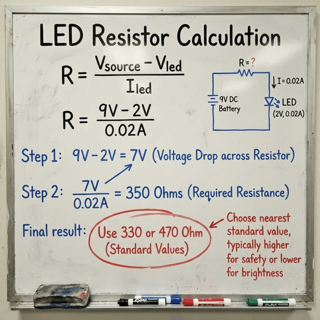
Here is the problem. An LED (Light Emitting Diode) is a fragile diva. It typically needs about 2V to turn on. If you connect it directly to a 9V battery, what happens?
Equation: The LED has very low resistance once it turns on (let’s say nearly 0 ). .
Poof. The LED explodes.
We need a resistor to “eat up” the extra voltage and limit the current to a safe level (usually 20mA or 0.02A).
We need to get rid of 7 Volts (). We want the current to be .
Using Ohm’s Law:
We don’t have a resistor. The closest standard values are 330 or 470.
Let’s pick 330 (or 220 if that’s all you have, it’s close enough for a demo).
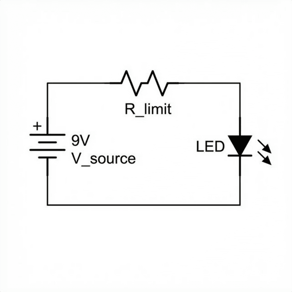
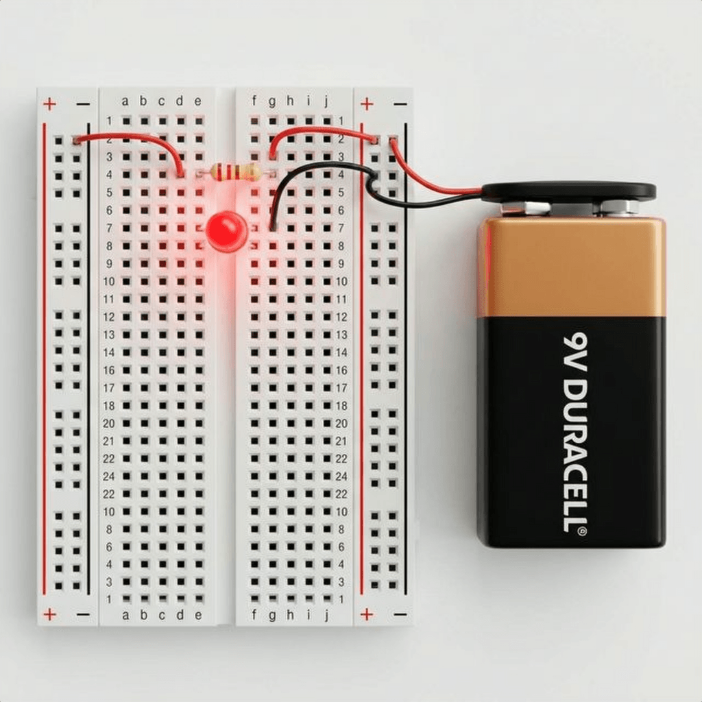
Let’s wire this up.
Why this order? It actually doesn’t matter! The resistor can go before or after the LED. The current is the same everywhere in the loop (Day 2 Lesson!).
Science isn’t about trusting math; it’s about verifying it.
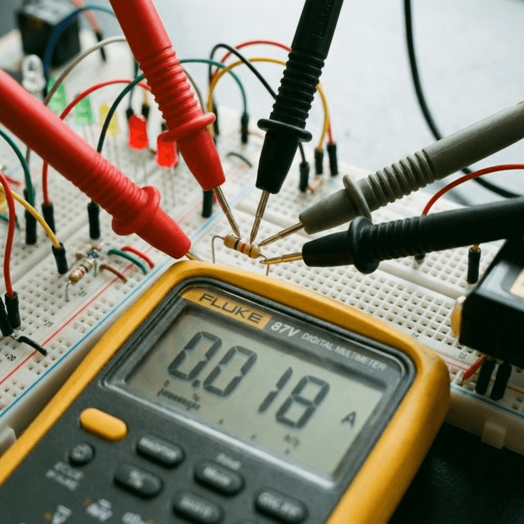
Set your Multimeter to DC Current (A or mA mode). Remember Day 2? You must break the circuit to measure current.
The Reading: If you used a resistor, you should see roughly: or 21mA.
If you see 0.021, you have successfully manipulated the laws of physics to your will.
Resistors behave very differently depending on how you connect them. This is the foundation of all circuit design.
When you connect resistors end-to-end, they form a single path. The electrons have to trudge through the first resistor, and then the second one. It is like adding more kinks to the same hose. The resistance adds up.
Example: If you have two resistors in series: . This is useful if you don’t have the exact resistor value you need. Need ? Just chain two s together!
When you connect resistors side-by-side, you create multiple paths for the electrons to flow. It is like opening a second lane on a highway. Even if the second lane is narrow (high resistance), it still improves the total traffic flow. Therefore, adding a resistor in parallel decreases the total resistance.
Formula:
Example: Two resistors in parallel. It cuts the resistance in half!
We mentioned that resistors convert electrical energy into heat. But how much heat can they handle? This is measured in Watts. Standard resistors in your kit are rated for 1/4 Watt (0.25W).
If you push more power than that, they will smoke, turn black, and fail (usually open circuit).
Substituting Ohm’s Law (), we get the two most useful forms:
Let’s check our LED circuit:
Verdict: is less than . You are safe! But if you used a resistor at 9V… Result: Instant fire. Always check the wattage.
Not all resistors are created equal.
You don’t need to memorize this, but you should understand how to read it.
| Color | Digit | Multiplier | Tolerance |
|---|---|---|---|
| Black | 0 | x1 | - |
| Brown | 1 | x10 | 1% |
| Red | 2 | x100 | 2% |
| Orange | 3 | x1k | - |
| Yellow | 4 | x10k | - |
| Green | 5 | x100k | 0.5% |
| Blue | 6 | x1M | 0.25% |
| Violet | 7 | x10M | 0.1% |
| Grey | 8 | - | - |
| White | 9 | - | - |
| Gold | - | x0.1 | 5% |
| Silver | - | x0.01 | 10% |
Example: Red - Red - Brown - Gold
This is a concept that confuses every beginner, but it is crucial for Arduino buttons.
The Floating Pin Problem: If you have an Arduino pin connected to a button, and the button is not pressed… what is the voltage? Is it 0V? Is it 5V? Answer: Neither. It is “floating”. It acts like an antenna, picking up static noise from the air. Your Arduino will read random 1s and 0s.
The Solution: We use a resistor (usually ) to “pull” the voltage to a known state when the button is open.
Without these resistors, digital logic simply does not work.
Resistors are generally reliable, but they do fail.
The understanding of resistance didn’t happen overnight.
1827: Georg Ohm A German physicist who was originally a high school teacher. When he published his book Die galvanische Kette, mathematisch bearbeitet (The Galvanic Circuit Investigated Mathematically), he was ridiculed. The scientific establishment believed electricity was a fluid that couldn’t be described by simple math. He was forced to resign his teaching post. It took decades for the world to realize he was right. Today, “Ohm” is the SI unit of resistance.
1833: The Wheatstone Bridge Samuel Hunter Christie invented it, but Charles Wheatstone made it famous. It’s a diamond-shaped circuit of four resistors used to measure unknown resistance with incredible precision. It is still used today in strain gauges (digital scales) to measure the tiny changes in resistance when a metal bar bends.
1885: The Carbon Composition Bradley patented the molded carbon resistor. Before this, resistors were made of long, coiled wires (which were expensive and bulky). Carbon resistors allowed mass production of radios and eventually, computers.
1959: The Integrated Circuit Jack Kilby and Robert Noyce figured out how to etch resistors directly onto silicon. This killed the vacuum tube and gave birth to the microchip.
What if you want to change resistance on the fly? You use a Potentiometer (Pot). It has a resistive track (carbon) and a “wiper” that slides along it.
Applications:
You have a multimeter, but what if you want to build your own? Technically, an Arduino cannot measure resistance directly. It can only measure voltage (0-5V). But using a Voltage Divider, we can calculate resistance.
Connect a known resistor (e.g., ) and your unknown resistor in series between 5V and GND. Connect the middle point to Analog Pin A0.
We can rearrange this to find the unknown:
Here is a sketch to turn your Arduino into a resistance meter:
// Simple Arduino Ohmmeter
// Connect Known Resistor (1k) between 5V and A0
// Connect Unknown Resistor between A0 and GND

const int sensorPin = A0;  // The middle of the voltage divider
const float Vin = 5.0;     // Input voltage
const float R_known = 1000.0; // Value of the known resistor (1k)

void setup() {
  Serial.begin(9600);
  Serial.println("Resistance Meter Ready...");
}

void loop() {
  int rawValue = analogRead(sensorPin);

  // Convert 0-1023 range to 0-5V
  float Vout = rawValue * (Vin / 1023.0);

  // Prevent division by zero if nothing is connected
  if (Vout > 0.1) {
    // Calculate Unknown Resistance
    float R_unknown = (Vout * R_known) / (Vin - Vout);

    Serial.print("Vout: ");
    Serial.print(Vout);
    Serial.print("V | Resistance: ");
    Serial.print(R_unknown);
    Serial.println(" Ohms");
  } else {
    Serial.println("No Resistor detected.");
  }

  delay(1000); // Update every second
}
Try measuring your resistor with this. It won’t be as perfect as your multimeter (because resistors have a 5% tolerance), but it proves you can digitize the physical world!
Ohm’s Law isn’t just a rule for preventing explosions. It is a tool for Linear Control.
Try swapping the resistor for a 10k (10,000 Ohms). (0.7mA). The LED will be barely visible.
By changing resistance, we change the outcome.
All of analog electronics is just clever ways of changing R to control V and I.

Understand electrical current like a pro. From drift velocity to safety, master the flow of electrons in Day 2 of our Analog Electronics series.
Read More →
Demystify voltage once and for all. Explore the physics, history, and practical measurement of electrical potential in this deep-dive guide for analog electronics beginners.
Read More →
Stop fearing the 100-page PDF. A software developer's guide to navigating hardware datasheets, identifying critical constraints, and mastering component documentation.
Read More →