The Great Restrictor: Mastering Resistance & Ohm's Law
Stop burning out your LEDs. Master electrical resistance, Ohm's Law calculations, and build your first protected circuit in Day 3 of our Electronics series.
Read More →
* SYSTEM.NOTICE: Affiliate links support continued laboratory research.
Welcome to Day 1 of the 75-Day Master Analog Electronics Course. If you have ever stared at a battery and wondered why one says “1.5V” and another says “9V,” you are not alone.
Every great engineer started exactly where you are today: confused by the invisible pressure that makes our modern world work. Voltage is the first step in unlocking the secrets of the physical world.
In the software world, we deal with logic, state, and flow. In the hardware world, before we can have any of that, we must have Potential. Voltage is that potential energy state.
It is the “pressure” that makes everything else possible. Without it, your circuits are just dead clusters of silicon and copper. This course is a 75-day journey designed for true design mastery.
By the end of this deep-dive guide, you won’t just know the academic definition of a Volt. You will feel the intuitive pressure of potential energy inside your wires and know how to tame it.
Master this, and the rest of the course will fall into place with a logical elegance you never thought possible. This is where your journey into the heart of hardware and physical reality begins.

Most textbooks start with the mathematical definition: . While technically correct, it’s a terrible way to start learning. Instead, let’s look at the world around us for a better model.
Imagine a ball sitting on a flat floor. It has no reason to move. It’s at rest, and its potential energy is zero relative to the floor. Now, imagine you pick that ball up and place it on a hill.
By lifting the ball, you have done work. That work is now stored in the ball as Gravitational Potential Energy. The ball “wants” to roll down. It is under pressure from the gravity field.
Voltage is the height of that hill. In electronics, we aren’t lifting balls; we are “lifting” electrons. A battery uses chemical reactions to pull electrons away from the positive electrode side.
It crams them into the negative terminal, creating a state of high electrical pressure. This pressure is the engine of all work. Without it, the electrons remain dormant in your copper wires.

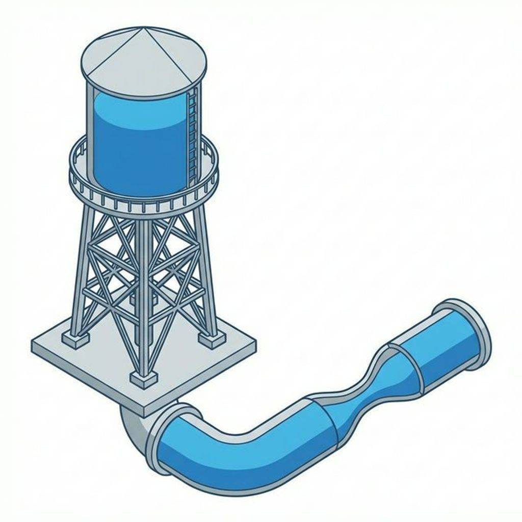
If you want to master analog electronics, you must become a master of the Water Analogy. It is the single most effective tool for debugging complex circuits in your head instantly.
Think of a massive water tower standing high above a city. Voltage is the Height of the water. Current is the Flow. Resistance is the Pipe Width restricting that flow.
If the water tower is 100 feet tall, the pressure at the bottom is high. If you open a valve, the water will spray out with great force. If the tower is only 5 feet tall, the pressure is low.
If the valve at the bottom of the tower is closed, the pressure is Static. It is still 100 PSI at the base, even though there is zero flow. This is like a battery sitting on your desk.
Once you open the valve and water starts flowing, the pressure might drop slightly because of friction in the pipes. In electronics, we call this Dynamic Pressure, similar to voltage sag.
Crucially, notice that you can have pressure without any flow. Pressure is a state; flow is an action. If you don’t have the “height” (Voltage), you will never get the “flow” (Current).
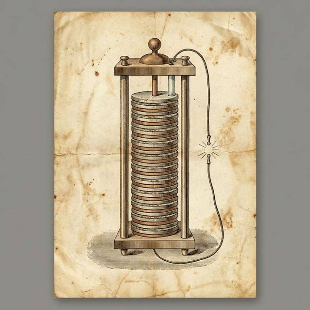
The story of voltage begins in the late 18th century. An Italian physician named Luigi Galvani was dissecting a frog leg. He noticed it twitched when touched by different metal tools.
Galvani believed he had discovered “animal electricity.” His friend Alessandro Volta was skeptical. Volta suspected the electricity came from the contact of different metals through moisture.
To prove it, Volta built the Voltaic Pile by stacking zinc and copper disks. This was the world’s first modern battery. In 1881, the unit was officially named the Volt in his honor.
Before the modern Volt was standardized, scientists used the Weston Standard Cell, a chemical battery with a very stable 1.0186V output, as the reference for all other measurements.
One of the earliest stable sources was the Daniell Cell, invented in 1836. It used copper and zinc electrodes in separate sulfate solutions, providing a steady 1.1V for telegraph systems.
Starting in the 1960s, a more fundamental reference emerged based on the Josephson Effect, where a voltage is generated across a superconductor junction exposed to microwave radiation.
A Volt is defined as the potential difference between two points that imparts one Joule of energy per Coulomb of charge. Mathematically: .
One Coulomb is approximately electrons. If you have a 12V car battery, every “clump” of electrons that moves is carrying 12 Joules of work energy throughout the car.
In the microscopic world, a single charge creates a potential at a distance . This is the absolute hill height at a distance from a single electron: .
Here, is Coulomb’s constant. Notice that as you get closer to a charge, the voltage (pressure) becomes incredibly high. This is what keeps atoms held together in a lattice structure!
This is the most common mistake beginners make. You cannot ask “What is the voltage at this point?” without providing a reference. It’s like asking “What is the height of this mountain?”
In electronics, we call our “sea level” Ground (GND). Ground is our 0V reference point. When we say a pin is “at 5V,” we mean there is a 5V potential difference to Ground.
A voltage is “floating” when it is not referenced to Ground. It’s like a hill hovering in mid-air. It’s unpredictable and noisy. This is why we use pull-up resistors to “anchor” our signals.
Without a solid reference, your circuit’s logic levels can drift randomly, leading to “ghost” triggers and unpredictable behavior in sensitive digital or analog systems alike.

Voltage doesn’t just sit there; it creates an Electric Field (). If you have two metal plates separated by a distance with a voltage across them, the field strength is .
If you have 100V across a 1mm gap, the field is 100,000 Volts per meter! This field is what actually exerts force on the electrons. If the field becomes strong enough, it can rip electrons right out of their atoms, causing Dielectric Breakdown (a spark).
The strength of this field is influenced by the Permittivity () of the material between the plates. Higher permittivity allows for more “stored” potential for the same field strength.
This is why smaller high-speed chips run at lower voltages like 0.8V; the distances are so tiny that even a small voltage creates a massive, potentially destructive electric field inside the silicon gates. Without this force, no current would ever flow through your logic circuits.
Where does this “pressure” from? In the analog world, there are several key ways we generate potential difference. Each source has unique characteristics in terms of stability and noise.
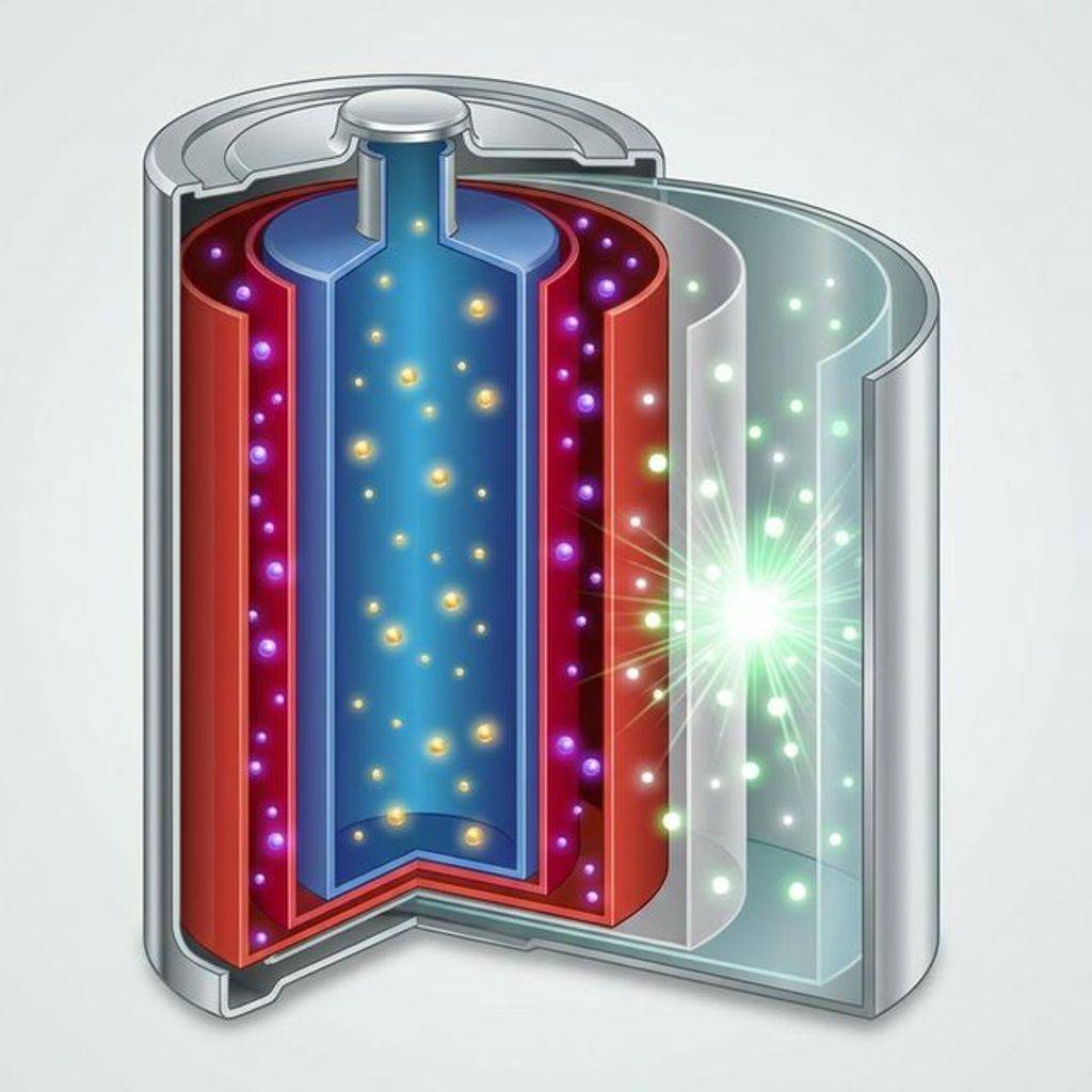
Inside a battery, a chemical reaction takes place between electrodes. Every battery has Internal Resistance ()—physical obstacles that resist the reaction, stealing some voltage.
The internal chemistry determines the nominal voltage; for example, Lead-Acid is 2.1V per cell, while Lithium-Cobalt is 3.7V. This internal physics determines the “strength” of the battery.
A real battery is an ideal voltage source () in series with its internal resistance (). When you connect a load (), the output voltage () drops according to: A 9V battery might have an of 2. If you draw 1A of current, the terminal voltage drops to . This theft of potential is converted into heat inside the battery lattice.
Voltage sources are not static. The potential produced by a chemical cell changes with temperature. Most batteries have a negative temperature coefficient, meaning their internal resistance increases as they get colder. This is why a car battery that works perfectly in the summer might fail to provide enough starting voltage (pressure) on a freezing winter morning in the north.
Even under ideal conditions, voltage sources drift over time. This is caused by chemical aging, moisture absorption, and thermal cycling. Precision systems use Voltage References (like the LM399) that are heated to a constant internal temperature to minimize this drift.
This thermal stability is critical for high-resolution measurement systems where a 0.01% drift in the reference voltage could translate into an unusable reading from a sensitive sensor.
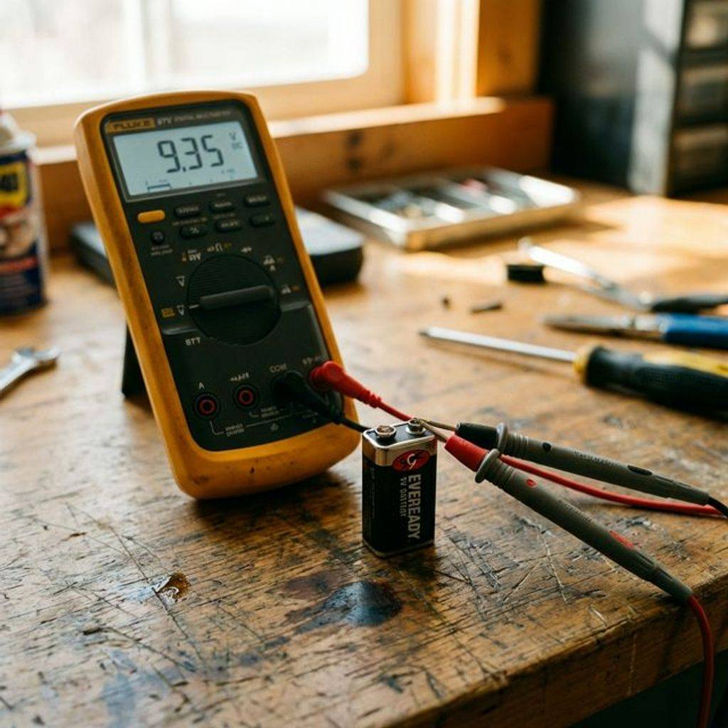
It’s time to get your hands dirty. We are going to use a Digital Multimeter (DMM) to measure real potential. This is the single most important tool in an electrical engineer’s bag.
Don’t skip the “COM” step; it’s the foundation of your measurement. A poor ground connection in your meter leads to phantom readings and frustration.
Crucial Rule: Voltage is always measured in Parallel. You bridge the two points you want to compare. Never break the circuit to measure voltage; just touch the test points.
Measure a 9V battery: black to negative, red to positive. Swap the probes—you’ll see -9V. This proves voltage has Polarity. The sign tells you which way the hill slopes (down vs up).
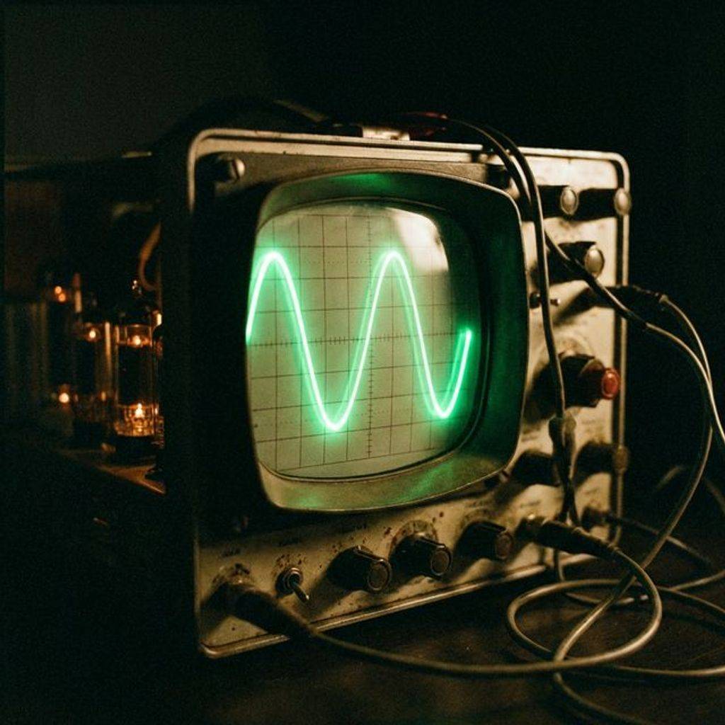
In this course, we mostly focus on DC (Direct Current). DC voltage stays at a constant level like a battery. However, you must understand AC (Alternating Current) early on.
Since AC wiggles, we use RMS (Root Mean Square) to describe it. A 120V AC outlet actually peaks at near 170V. But it does the same work as a constant 120V DC source would.
This mathematical conversion is vital for understanding power delivery. Heating elements and light bulbs respond to the energy (RMS) of the wiggle, not just its highest instantaneous peak.
AC is defined by its Frequency, measured in Hertz (Hz). 60Hz means 60 wiggles per second. Higher frequencies are used in radio and switching power supplies to keep parts small and light.
We can generate voltage from the environment in surprising ways. The Seebeck Effect occurs when two different metals are joined at different temperatures, creating a small voltage. This is the foundation of the Thermocouple, a sensor used to measure everything from engine heat to kiln temperatures. By stacking these junctions (a Thermopile), we can actually generate power from waste heat, a process used in deep-space missions where sunlight is unavailable.
Another fascinating phenomenon is the Piezoelectric Effect. Certain crystals, like quartz or lead zirconate titanate (PZT), generate a voltage when they are mechanically squeezed or stretched. This is what creates the high-voltage spark in a barbecue lighter. It is also used in high-precision sensors like microphones and ultrasonic transducers, where tiny mechanical vibrations are converted directly into measurable electrical potential signals for our computers to process.
Before transistors, we used Vacuum Tubes to control voltage. A tube works by heating a filament to boil electrons off into a vacuum. A metal grid between the emitter and collector acts like a valve. By applying a small voltage to this grid, you can control a much larger voltage flow. This “Space Charge” control allowed for the birth of radio and early computing. While bulky and hot, tubes laid the groundwork for the field-effect theory we use in modern silicon chips.
One of the most important theories you will ever learn is KVL. It states that the sum of all voltages in a closed loop must equal zero. Think of it as conservation of energy. If you climb up a 9V hill (the battery) and then slide down some smaller hills (the resistors), you must end up exactly where you started—at the bottom. Mathematically, for a single loop: This means if you have a 9V battery and two identical resistors in series, each resistor must drop 4.5V. The energy given by the source is entirely consumed by the path. If you measure the voltage around a loop and it doesn’t add up to zero, you have missed a hidden component!
In the US, home power is “Split-Phase.” Two 120V lines relative to a center Neutral are provided. Appliances between hot and neutral see 120V. Between both hot lines, they see 240V.
This higher “pressure” is used for ovens to reduce current and heat. Since , doubling the voltage allows for thinner, cheaper wires. It’s an essential lesson in infrastructure efficiency.
When running long wires, we must account for Cable Voltage Drop. Copper has a resistivity (). A long extension cord has a resistance . If you draw a current , the voltage at the far end () is reduced by the current times the wire resistance: If you try to run a 1,500W heater () on a 100ft thin 16AWG cord ( round trip), you lose in the cord alone! This energy is wasted as heat, which can actually melt the insulation. This is why high-voltage transmission is favored for long-distance power grids.
When you measure a voltage with a multimeter, you are actually connecting a massive resistor in parallel with the circuit. This is called the Input Impedance (). Most modern digital multimeters have a of .
If your circuit also has high resistance (like a mega-ohm sensor), the meter itself will pull some current and “sag” the voltage you are trying to measure. This is called Meter Loading Error. To avoid this, high-precision analog design requires using buffer amplifiers or high-impedance FET-input probes to ensure the measurement doesn’t alter the reality of the circuit state.
When reporting a voltage, precision matters. A reading of “5V” on a cheap meter might mean anywhere from 4.5V to 5.5V. A laboratory-grade 6.5-digit multimeter will show “5.000000V,” providing confidence in the seventh decimal place.
This accuracy is vital for high-resolution Analog-to-Digital Converters (ADCs), where a tiny bit of noise or drift can represent a massive error in the digital data being processed. Always check the “Basic Accuracy” specification of your meter before trusting a critical reading.
High voltage is not just a shock hazard; it is an explosion hazard. When a high-voltage source shorts through the air, it creates an Arc Flash. The air turns into a plasma hotter than the surface of the sun.
This vaporizes the metal wires, expanding their volume by thousands of times instantly. This “Arc Blast” can throw an engineer across a room and cause severe pressure injuries. This is why high-voltage technicians wear thick, multi-layer fire-resistant suits and face shields during work.
How do we keep a voltage stable if the battery is dying or the load is changing? We use a Voltage Regulator. A Linear Regulator (like the 7805) acts like a dynamic resistor that “burns off” excess voltage as heat to maintain a constant output.
A Switching Regulator (Buck Converter) is much more efficient; it “chops” the input voltage into high-speed pulses and uses an inductor to smooth it back out to a lower DC level. This is the difference between a simple resistor and a sophisticated energy distribution system.
When you suddenly cut the voltage to an inductor (like a motor or a relay coil), the collapsing magnetic field tries to keep the current flowing. This creates an massive, instantaneous voltage spike in the opposite direction, known as Flyback Voltage. V_L = L \cdot \frac{di/dt} If the time is near zero, the voltage can reach thousands of Volts, instantly frying any nearby transistors or microcontrollers. This is why we always include Flyback Diodes in parallel with inductive loads to provide a safe “drain” for this sudden, violent release of energy.
In advanced sensor design, we often care about the difference between two signals rather than their relation to Ground. Differential Voltage is the 5mV signal from a heart cell.
Common-Mode Voltage is the 60Hz hum from the wall outlet that appears on both sensor wires. By using a Differential Amplifier, we can reject the common noise and amplify only the tiny biological signal we want. This “Common-Mode Rejection Ratio (CMRR)” is the holy grail of high-precision analog design, allowing us to see signals that would otherwise be lost in noise.
CMRR is measured in decibels (dB), with higher values indicating better noise rejection. An Op-Amp with 100dB CMRR can suppress a 10V common-mode noise signal down to 100 microvolts at the output, allowing the tiny differential signal to be clearly processed by the system.
In an ideal Op-Amp, the output is zero if the inputs are tied together. In reality, a small Input Offset Voltage () exists due to manufacturing mismatches in the internal transistors.
Even a tiny of 1mV can be amplified by a gain of 1,000 to create a massive 1V error at the output. Precision design requires choosing “Low Offset” parts or using external trimming circuits.
How fast can a voltage change? In amplifiers, this is limited by the Slew Rate. If you apply a square wave, the output can’t jump instantly; it “slides” up at a fixed rate (e.g., ).
This is caused by the internal charging of compensation capacitors. If the signal changes faster than the slew rate, the result is signal distortion and “ringing,” which can be fatal for high-speed data.
In circuit analysis, we use Dependent Sources to represent the behavior of transistors. A Voltage-Controlled Voltage Source (VCVS) takes an input voltage and outputs a scaled version.
A Voltage-Controlled Current Source (VCCS) is the model for a MOSFET, where the gate-to-source voltage () controls the drain current (). Mastering these abstractions allows you to model complex integrated circuits as simple sets of mathematical potential relationships.
Why do we care if the voltage is 5V or 10V? Because of Power (). When you double the voltage across a resistor, the power dissipated (heat) quadruples.
This square relationship is why voltage regulation is so critical. A small spike in voltage can lead to an exponential increase in thermal stress, which is the primary cause of component failure.
In Bipolar Junction Transistors (BJTs), the collector current is not perfectly independent of the collector-emitter voltage (). As increases, the effective base width decreases.
This is known as the Early Effect. It causes the collector current to rise slightly as output voltage increases, which is modeled as a finite Output Resistance (). This effect limits the maximum voltage gain an amplifier can achieve and is a key factor in precision analog design.
When a voltage gain () exists across a capacitor connected between the input and output of an amplifier, the effective input capacitance becomes times the physical capacitance.
This is known as the Miller Effect. It can dramatically reduce the high-frequency response of an amplifier by creating a dominant pole at the input. Controlling this effect is a primary challenge in high-speed analog design, often requiring the use of cascode amplifier topologies.
No voltage is perfectly clean. Johnson-Nyquist Noise is the random voltage fluctuations caused by the thermal motion of electrons inside resistors. It is defined as .
This means every resistor in your circuit is actually a tiny, noisy voltage source! In high-gain audio or sensor circuits, this thermal noise floor determines the limit of what you can measure.
Another common issue is Capacitive Coupling. When two wires are close together, the changing voltage on one can “leak” into the other through stray capacitance. This is the source of “crosstalk” in old telephone lines and digital signal interference in modern high-speed circuit boards.
To fight this, we use Grounding Strategies. We often separate Analog Ground from Digital Ground to keep the noisy switching pulses of the CPU from corrupting the tiny, sensitive analog signals of our sensors. Proper grounding is an art form that separates experts from amateurs.
Inside a silicon diode or transistor, voltage creates a Depletion Region. This is a layer where no mobile charges exist. When you apply a “Reverse Bias” voltage, this region grows wider, acting like a closed valve. When you apply a “Forward Bias” voltage of around 0.7V, the pressure is high enough to collapse this region and allow flow. This 0.7V “Barrier Potential” is a physical constant of silicon and is the reason your circuits need a minimum pressure to work.
Sometimes we need to pass a signal between two circuits that have completely different Ground references. This is common in high-voltage industrial systems or medical devices. We use Galvanic Isolation to provide a physical gap that voltage cannot jump across safely.
Optocouplers use light to send signals across a gap, while pulse transformers use magnetic fields. This prevents a high-voltage fault on one side from ever reaching the sensitive low-voltage brain on the other side, ensuring both user safety and equipment longevity in harsh environments.
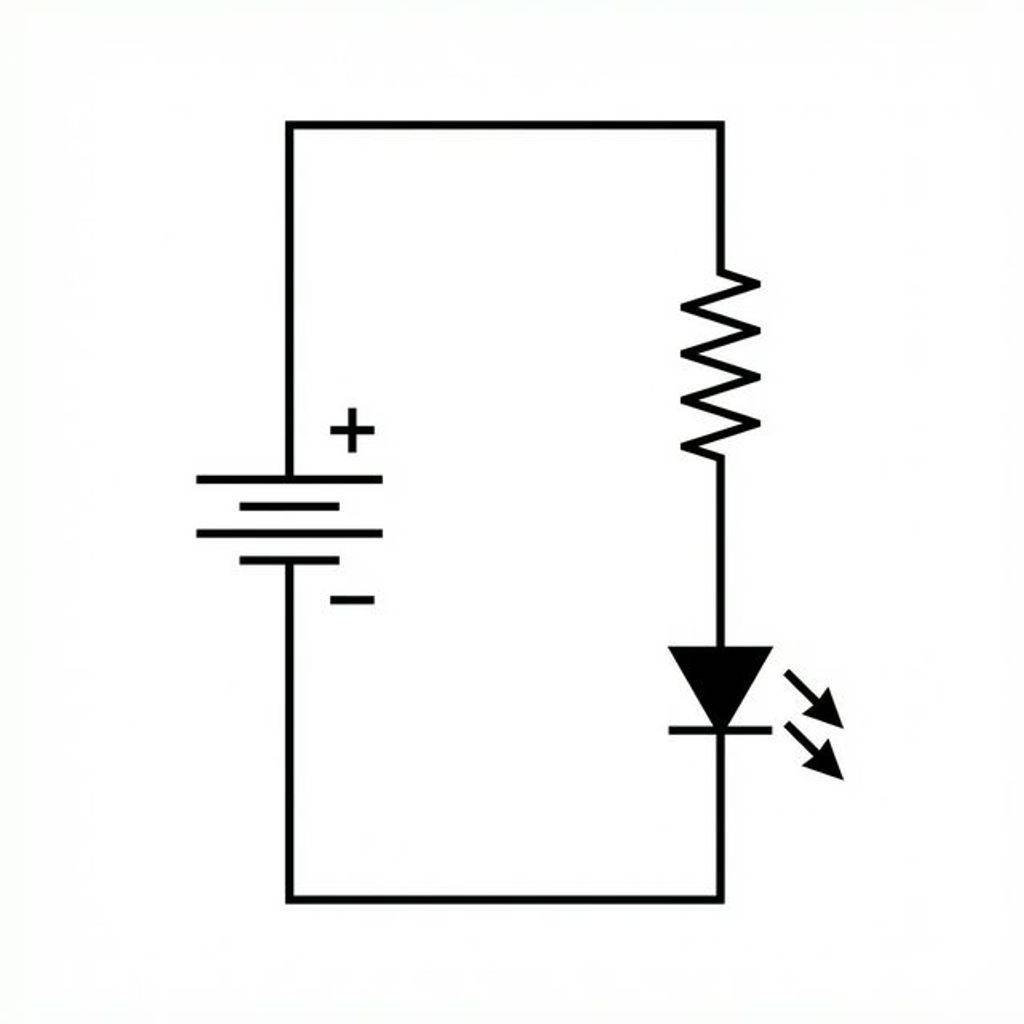
We aren’t going to do complex math yet; we just want to see potential turn into light. This is the simplest circuit to build to visualize the “invisible force” in action on your breadboard.
The circuit is a loop: Positive (9V) Resistor (1k) LED Negative (GND). When connected, you create potential difference. Electrons are “pushed” through.
If you swap the LED, it won’t light—LEDs are directional. The resistor protects the LED from the high pressure of the 9V battery. Always use a resistor to “throttle” the energy to a safe state.
Bandgap References: Modern chips use silicon’s physical properties to create a stable reference voltage that doesn’t change with heat. This is critical for precision sensors and ADCs. Breakdown Voltage: Every insulator has a limit. Air breaks down at 3kV/mm. Ceramics take millions of volts. Choosing the right “Dielectric Rating” prevents catastrophic system failures. Multimeter Anatomy: Modern digital meters use a high-impedance divider network. This reduces high voltage to a level the internal Analog-to-Digital Converter can safely handle for you.
| Chemistry | Cell Voltage | Energy Density | Note |
|---|---|---|---|
| Alkaline | 1.5V | Medium | Standard disposable cell |
| Silver Oxide | 1.55V | High | Small watch/button cells |
| NiMH | 1.2V | Medium | Common rechargeable AA/AAA |
| Li-Ion | 3.7V | Very High | Phones, Laptops, Cars |
| Lead Acid | 2.1V | Low | Car ignition, heavy storage |
| LiFePO4 | 3.2V | High | Safe, long-life solar banks |
TTL Logic: Standard 5V or 3.3V levels. Defined as 1 or 0 by certain voltage thresholds. RS-232: Uses +/- 12V swings for old-school serial communication over long cables. USB Power: Modern USB-C can negotiate up to 48V at 5A for fast-charging laptops. VCC/VDD Labels: Understand what the letters mean: Vcc (Collector Supply), Vdd (Drain Supply), Vee (Emitter Supply), and Vss (Source Supply). They tell you where the “hill” connects.
Voltage is the potential for action. Electricity is nature trying to get back to Ground (0V). Without voltage, your smartphone is just a glass paperweight. Today you learned to see the pressure.
Homework Challenge:
Q: Can I measure the wall outlet directly? A: ONLY with a CAT II+ rated meter. It is extremely dangerous for beginners and can be lethal. Q: Is static electricity high voltage? A: Yes, up to 30,000V! But it has almost no charge current, so it’s rarely lethal to humans. Q: Do electrons move at light speed inside a wire? A: No, individual electrons move quite slowly. The electromagnetic “wave” moves at light speed. Q: Can voltage be negative relative to Ground? A: Yes. It just means the potential is lower than your reference 0V sea level.

Stop burning out your LEDs. Master electrical resistance, Ohm's Law calculations, and build your first protected circuit in Day 3 of our Electronics series.
Read More →
Understand electrical current like a pro. From drift velocity to safety, master the flow of electrons in Day 2 of our Analog Electronics series.
Read More →
Stop fearing the 100-page PDF. A software developer's guide to navigating hardware datasheets, identifying critical constraints, and mastering component documentation.
Read More →