The Great Restrictor: Mastering Resistance & Ohm's Law
Stop burning out your LEDs. Master electrical resistance, Ohm's Law calculations, and build your first protected circuit in Day 3 of our Electronics series.
Read More →
* SYSTEM.NOTICE: Affiliate links support continued laboratory research.
If you’re like me, the word “Law” in a technical context usually implies one of two things: a confusing legal requirement or a boring physics equation you memorized in high school and promptly forgot. As a software developer, you’re used to abstract logic, complex state machines, and high-level APIs. You don’t usually need to worry about the laws of physics—until you try to light up an LED and it explodes in a tiny puff of “magic smoke.”
Welcome to the world of Ohm’s Law.
In this sixth installment of our “Software Developer’s Hardware Journey,” we are going to tackle the only math you genuinely need to thrive in hardware. Forget calculus. Forget linear algebra. Ohm’s Law is basically simple arithmetic, but its implications are the difference between a working project and a trip to the trash bin.
Think of Ohm’s Law as the “Big O Notation” of the physical world. Just as Big O helps you understand the scalability and constraints of your code, Ohm’s Law helps you understand the constraints and behavior of your electrons.

In the physical world, every circuit is governed by the relationship between three fundamental properties: Voltage (V), Current (I), and Resistance (R).
If you’ve spent any time in a terminal, you know that (conceptually). Electronics has a similar fundamental relationship.
In our software world, think of Voltage as Stack Depth or Potential Energy. It is the “pressure” that wants to make things happen. It’s measured in . A battery has more “push” than a AA battery.
If you visualize a water tank on a tower, Voltage is the height of that tower. The higher the tank, the more pressure there is at the bottom of the pipe.
In physical terms, Voltage is the difference in potential energy between two points. This is why we always measure it “across” a component. There is no such thing as “Voltage at a point” without a reference point (usually Ground).

Current is the actual movement of electrons through the wire. It’s measured in Amperes (). If Voltage is the pressure, Current is the volume of water moving through the pipe per second.
As developers, we can equate this to Request Rate or Throughput. If you have a high “push” (Voltage) and no constraints, you’ll have massive “flow” (Current).
It’s critical to note that current comes in two flavors:
For our breadboard journey, we are 100% focused on DC.
Resistance is what makes things interesting. It is the property of a material to oppose the flow of current. It’s measured in .
In software terms, this is your Rate Limiter or Network Latency. It’s the friction that prevents the Current from becoming infinite and melting your wires. A resistor is a component specifically designed to provide this friction.

This is it. The “Hello World” of electrical engineering. Ohm’s Law states that the Voltage across a component is equal to the Current flowing through it multiplied by its Resistance.
Or, as you’ll more commonly use it when designing a circuit:
If you ever struggle to remember this, just think of the Ohm’s Law Triangle. Cover the variable you want to solve for, and the remaining variables show you the math (if they’re side-by-side, multiply; if one is over the other, divide).

In software, if you pass too much data to a function, you might get a StackOverflowError or an OutOfMemoryException. In hardware, if you pass too much Current through a component, it physically breaks.
Imagine an LED. An LED is like a very fragile API. It has a “Maximum Input” (Current) that it can handle. Usually, this is around (). If you connect a power supply directly to an LED without a resistor, the Resistance of the LED itself is nearly zero.
According to our math:
Obviously, you don’t actually get infinite current, but you get way more than 20mA. The LED heats up instantly, the internal semiconductor material melts, and you get a hardware crash.

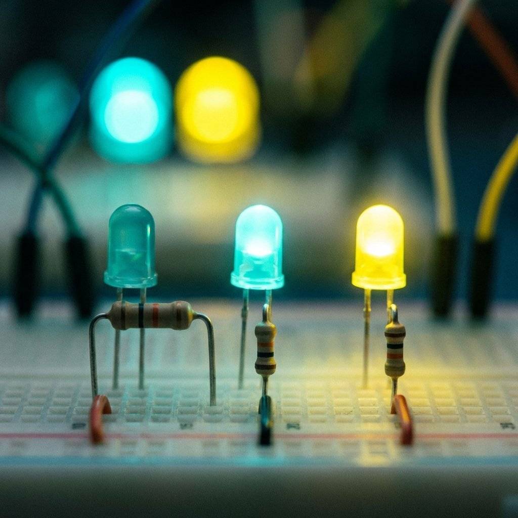
Let’s do some “Hardware Debugging.” We want to light up a standard Red LED using a power supply (common from an Arduino or USB port).
The Specs:
The Logic: First, we need to find the Voltage that the resistor needs to handle. The LED takes , so the resistor must drop the remaining .
Now, we use Ohm’s Law to find the Resistance ():
So, we need a resistor. If we use a higher value (like or ), the current will be lower, and the LED will be dimmer. If we use a lower value, the LED will be brighter—and potentially shorter-lived.
In software, we have YAML files and package.json to tell us what a library does. In hardware, resistors use Color Bands.
If you look closely at a resistor, you’ll see 4 or 5 colored stripes. This is not for decoration; it’s a encoded value.
Example: A resistor (common for LEDs):
Result: .
Example: A resistor (common for pull-ups):
Result: .
As a developer, you can think of the first two bands as the Mantissa and the third band as the Exponent. It’s effectively scientific notation in color form!
There’s one more formula you need to know, and it’s related to heat: The Power Law.
Power is measured in Watts (). Every component has a power rating. Standard resistors are usually rated for ().
If we calculate the power wasted by our LED resistor from earlier:
Since is much less than , the resistor will stay cool. If we were trying to drop at , the power would be , and a standard resistor would turn into a heating element (and then a fire hazard).
As a software dev, think of this as Resource Utilization. You want to make sure your hardware can handle the “load” you’re putting on it.
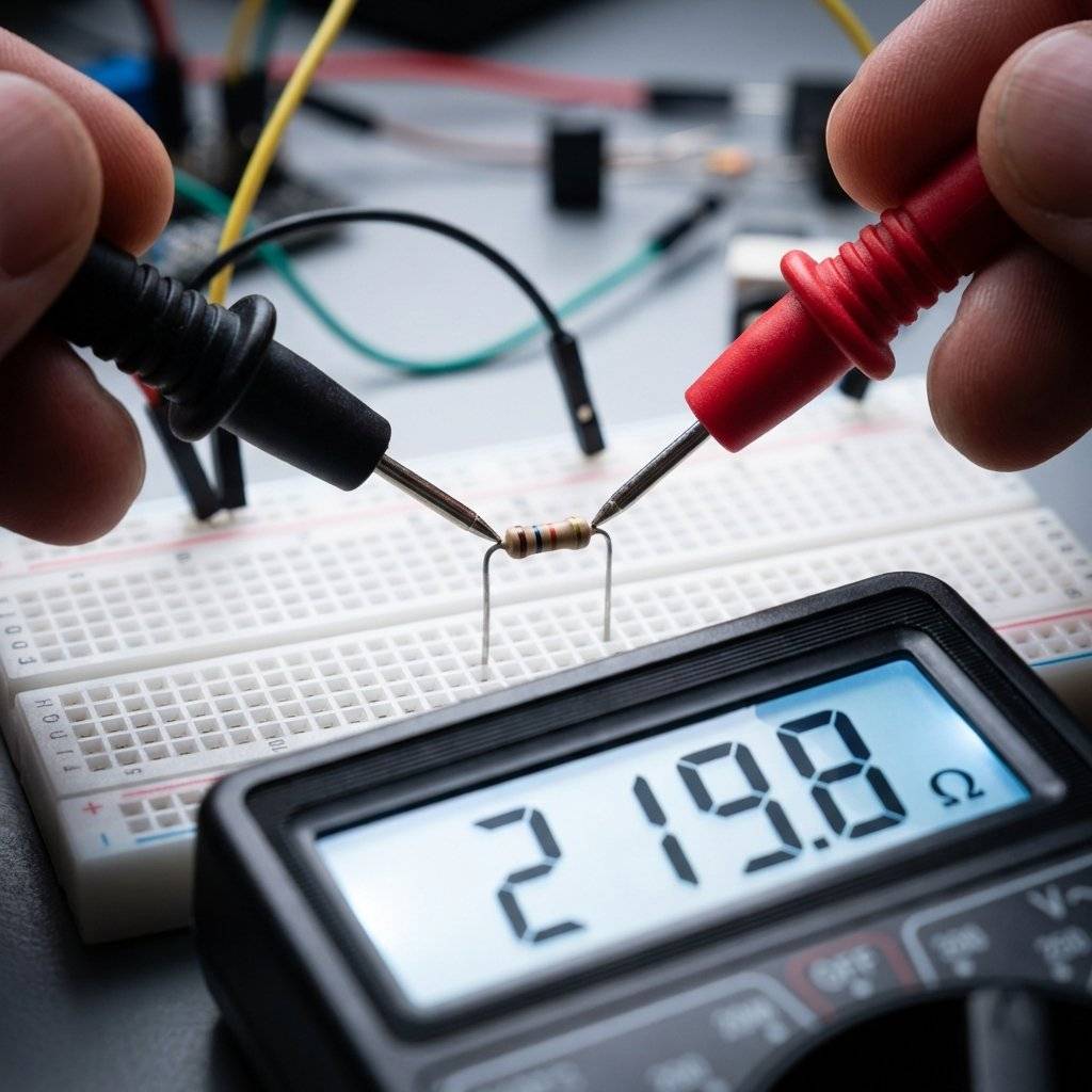
In VS Code, we set breakpoints and inspect variables. In hardware, we use a Multimeter.
A multimeter allows you to measure Voltage, Current, and Resistance in real-time. It is the single most important tool in your arsenal. When your circuit doesn’t work, don’t guess—measure.
If Ohm’s Law is the primitive, Kirchhoff’s Laws are the design patterns. They tell us how Ohm’s Law behaves in more complex systems.
KVL states that the sum of all voltages in a closed loop is zero. In software, this is like Memory Integrity. You can’t create energy out of nowhere. If you start with 5V, you must use exactly 5V by the time you reach Ground.
If your LED takes 2V, the resistor must take the other 3V. If there’s 1V left over, it means you’ve got a “leak” (unintentional resistance) or you’re violating the laws of physics.
KCL states that the total current entering a junction (node) must equal the total current leaving it. This is Data Flow Conservation. If 100mA enters a fork in your circuit, 100mA must come out the other side. You can’t drop packets (electrons) in a wire.
Even though is a “law,” the real world has some “edge cases” (just like your code).
Resistors get hot. When they get hot, their resistance can change. This is like Thermal Throttling on a CPU. In high-precision circuits, we use resistors with very low “Temperature Coefficients.”
Not everything follows Ohm’s Law perfectly. LEDs, transistors, and diodes are “non-ohmic.” Their resistance changes based on the voltage applied to them. Think of them as Asynchronous Functions—their behavior isn’t a simple linear line; it has a “threshold” or a “trigger point.”
If you try to draw too much current from a small battery, the Voltage will drop. This is the hardware equivalent of a Thread Pool Exhaustion. The pressure isn’t enough to keep up with the demand.
As a developer, you’ll encounter resistors most often when working with GPIO pins.
To fix this, we use resistors to “pull” the pin to a known state ( or GND).
. This is enough to hold the pin high but small enough to not waste power. When the switch closes, the pin goes to GND, and the resistor prevents a short circuit from to GND.
/*
 * Hardware vs Software Pull-ups
 *
 * You can do this in code (pinMode INPUT_PULLUP),
 * but knowing the Ohm's Law behind it makes you a better engineer.
 */

const int buttonPin = 2;

void setup() {
  // Using the internal 20k-50k resistor (Ohm's Law in the silicon!)
  pinMode(buttonPin, INPUT_PULLUP);
  Serial.begin(9600);
}

void loop() {
  int state = digitalRead(buttonPin);
  if (state == LOW) {
    Serial.println("Button Pressed: Path to GND established.");
  }
}
If you measure your circuit and Ohm’s Law seems to be broken, follow this checklist:
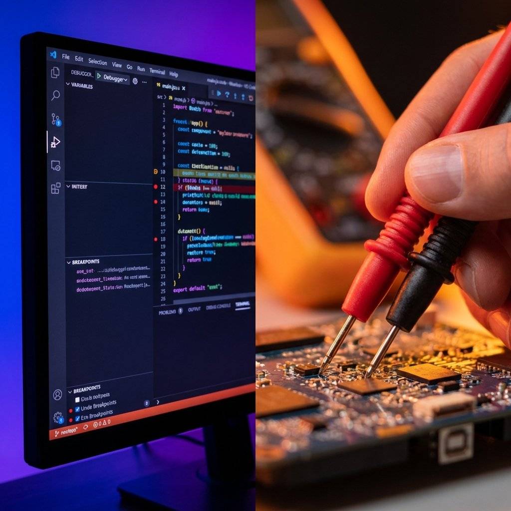
One of the hardest shifts for me was moving from “Logical Debugging” to “Physical Debugging.”
In code, if x = 5, then x is 5 everywhere in that scope. In hardware, if you have a loose wire on your breadboard, the “variable” (Voltage) might be 5V at the battery and 0V at the LED.
You have to trace the “execution path” (the wires) with your multimeter just like you trace a function call in a stack trace.
If the voltage disappears where it shouldn’t, you’ve found your “Hardware Bug.”
In software, a recursive function without a base case causes a stack overflow. In hardware, a path with zero resistance causes a Short Circuit.
$I = V / 0 = \text{BOOM.}$
A short circuit is when Current finds a path back to Ground with nothing to slow it down (no resistor, no component). It will draw as much current as the power supply can provide. Batteries can explode, wires can melt, and USB ports can be permanently damaged.
Rule Zero of Hardware: Always double-check your paths to Ground before applying power.
If Ohm’s Law is the primitive int, then Series and Parallel circuits are the arrays and objects.
Think of this as Pipe Chaining. Each segment adds its own latency.
This is like Adding More Worker Nodes. By adding more paths, you make it easier for the “traffic” (current) to flow. Two resistors in parallel act like a single resistor.
We call it Ohm’s Law today, but in 1827, Georg Ohm’s work was actually ridiculed. The scientific community at the time thought his mathematical treatment of light and electricity was a “web of naked fancies.”
Ohm was a high school teacher, not a university professor, and he spent his limited funds buying different types of wire to test his theories. He discovered that the “electromotive force” was directly proportional to the “magnitude of the current.”
It took decades for the world to realize Ohm hadn’t just found a curious phenomenon—he had found the foundation of the modern world. Every transistor in your CPU, every backlight in your phone, and every solar panel on a roof exists because Georg Ohm refused to stop measuring.
As developers, we are his intellectual descendants. We measure, we optimize, and we define the laws of our own digital universes.
| Term | Electrical Meaning | Software Analog |
|---|---|---|
| Open Circuit | High Resistance (Gap) | Null Reference / Broken Link |
| Short Circuit | Zero Resistance | Infinite Loop / Memory Leak |
| Potentiometer | Variable Resistance | Configuration Parameter / slider |
| Node | Junction of Wires | Event Bus / Main Branch |
| Load | Energy-consuming part | Application Logic |
| Tolerance | Resistor’s accuracy | Floating point precision |
| Wattage | Heating limit | CPU Thermal TDP |
| Oscilloscope | Waveform visualize | Flame Graph / Performance Profiler |
You’ll notice most modern microcontrollers use 3.3V, while older ones (like the original Arduino) use 5V.
Why the change? Ohm’s Law!
$P = V \cdot I$. If you lower the Voltage, you can lower the Power consumption for the same amount of computation. Lower power means less heat, which means you can pack more transistors (more logic) into a smaller space.
Moving from to was a massive “Efficiency Refactor” for the entire world of computing.
Ohm’s Law isn’t about memorizing a formula; it’s about developing an intuition for the flow of energy.
Once you understand that these three things are always in a dance, the “Magic Smoke” stops being a scary probability and becomes a controlled variable.

As you move forward, you’ll realize that Ohm’s Law is less of a calculation you perform and more of a “sanity check” you internalize. Just like you can spot an loop at a glance, you’ll soon be able to look at a circuit with a resistor and realize, “Wait, that’s … something is going to get hot.”
| Color | 1st Digit | 2nd Digit | Multiplier | Tolerance |
|---|---|---|---|---|
| Black | 0 | 0 | x1 | - |
| Brown | 1 | 1 | x10 | ±1% |
| Red | 2 | 2 | x100 | ±2% |
| Orange | 3 | 3 | x1,000 | - |
| Yellow | 4 | 4 | x10,000 | - |
| Green | 5 | 5 | x100,000 | ±0.5% |
| Blue | 6 | 6 | x1,000,000 | ±0.25% |
| Violet | 7 | 7 | x10,000,000 | ±0.1% |
| Grey | 8 | 8 | - | ±0.05% |
| White | 9 | 9 | - | - |
| Gold | - | - | x0.1 | ±5% |
| Silver | - | - | x0.01 | ±10% |
That intuition is the real goal. The math is just the tool we use to verify it. Now, go build something incredible—and keep the magic smoke inside the components where it belongs!
Detailed LED Forward Voltage (V_f) Reference
| Color | Material | Wavelength (nm) | Forward Voltage (V_f) |
|---|---|---|---|
| Red | GaAsP/GaP | 610 < λ < 760 | 1.6V - 2.0V |
| Orange | GaAsP/GaP | 590 < λ < 610 | 2.0V - 2.1V |
| Yellow | GaAsP/GaP | 570 < λ < 590 | 2.1V - 2.2V |
| Green | GaP | 500 < λ < 570 | 1.9V - 4.0V |
| Blue | InGaN | 450 < λ < 500 | 2.5V - 3.7V |
| Violet | InGaN | 400 < λ < 450 | 2.8V - 4.0V |
| White | InGaN (y-phosphor) | All λ | 2.8V - 4.0V |
Practical Calculations Reference Table
| Supply Voltage | LED Type | Target Current | Required Resistor | Closest Standard Value |
|---|---|---|---|---|
| 5V | Red (2V) | / | ||
| 5V | Blue (3.3V) | |||
| 3.3V | Red (2V) | |||
| 9V | Red (2V) | / | ||
| 12V | White (3.5V) |
Found this guide helpful? Check out the previous post on The Breadboard Sandbox to see where these circuits live!
Mastering Ohm’s Law is the first real step towards hardware independence. It shifts your perspective from being a consumer of modules to an architect of systems. You are no longer just connecting dots; you are managing the lifeblood of your technology.

Stop burning out your LEDs. Master electrical resistance, Ohm's Law calculations, and build your first protected circuit in Day 3 of our Electronics series.
Read More →
Understand electrical current like a pro. From drift velocity to safety, master the flow of electrons in Day 2 of our Analog Electronics series.
Read More →
Demystify voltage once and for all. Explore the physics, history, and practical measurement of electrical potential in this deep-dive guide for analog electronics beginners.
Read More →