The Great Restrictor: Mastering Resistance & Ohm's Law
Stop burning out your LEDs. Master electrical resistance, Ohm's Law calculations, and build your first protected circuit in Day 3 of our Electronics series.
Read More →
* SYSTEM.NOTICE: Affiliate links support continued laboratory research.
If you’ve ever opened an electronics datasheet and felt a sudden wave of vertigo, you aren’t alone.
To a software developer, a datasheet looks like a cross between a legal contract, a Calculus textbook, and a poorly formatted README.txt from 1994.
It’s dense.
It’s dry.
And it’s often 100 pages of information you didn’t think you needed.
But here is a secret: A datasheet is just a man page for an atom.
In the 8th chapter of our “Software Developer’s Hardware Journey,” we are going to conquer the final boss of hardware engineering: The PDF Document.
We’re going to learn how to scan, filter, and extract the exactly three pieces of information you actually need to stop your project from exploding.
Actually, think of it this way: As a developer, you would never start using a complex Amazon Web Services (AWS) API without checking the documentation for rate limits and payload structures.
Hardware is exactly the same, except the rate limit is enforced by heat and the payload structure is enforced by voltage.
When you open a datasheet—say, for the ubiquitous NE555 timer—the first page is your “Marketing README.”
It lists the features, the “Best For” scenarios, and the high-level capabilities.
As a dev, you should read this like a GitHub project description.
Does this library support async?
Does this chip support ?
If the first page says “Ultra-low power” and “Mobile applications,” you know you’re looking at something power-efficient.
If it says “High-current driver,” expect it to get hot.
This is the most important table in the entire document.
In software, if you pass a -1 to a function that expects an unsigned int, the compiler might complain, or the program might crash.
In hardware, if you pass a to a pin that expects , the chip physically melts.
The Absolute Maximum Ratings are the “Guard Rails” of reality.
If you exceed these values, even for a microsecond, the manufacturer no longer guarantees the chip will work.
In fact, they essentially guarantee it won’t work ever again.
As a dev, you should think of these as Runtime Exceptions that break the hardware physically.
There is no try-catch for an overvoltage spike.
You build the “Catch” in hardware using protection diodes and resistors.

Once you know how not to kill the chip, you need to know how it actually performs under pressure.
The Electrical Characteristics table is the “Benchmarks” section.
It tells you the Minimum, Typical, and Maximum performance.
As a software engineer, you should always design for the Worst Case (Min/Max), not the Typical.
If the “Typical” turn-on time is but the “Maximum” is , your code needs to be able to handle that delay, or you have a race condition waiting to happen.

How does a chip know that a voltage is a “1” or a “0”?
It’s not as simple as .
Datasheets define these as:
If your voltage falls between and , you are in Undefined Behavior territory.
In software, undefined behavior is a bug.
In hardware, it usually results in “Jitter”—the pin rapidly flickering between 1 and 0 because of electrical noise.
| Logic Level | TTL () | CMOS () |
|---|---|---|
| Logic HIGH () | ||
| Logic LOW () |
This gap (the “Noise Margin”) is the hardware equivalent of a buffer.
This is where the magic happens.
The Pinout diagram is your Class Interface.
Every pin is a public method or an instance variable.
power() and dispose() methods.Wait, why are there multiple GND pins on some chips?
In software, you don’t care where the trash goes.
In hardware, “Ground” is the path for the return current.
Multiple ground pins are like having multiple worker threads clearing the garbage to prevent a bottleneck and reduce impedance.

This is the part that usually makes software developers cry.
The Timing Diagram.
It looks like a bunch of squiggly lines horizontally aligned.
In reality, it is a visualization of a Race Condition.
It tells you: “You must set Pin A to HIGH, wait 10 nanoseconds for the internal gates to settle, then pulse Pin B to LOW.”
If you treat hardware like a synchronous blocking call, you will fail.
Hardware is inherently asynchronous.
The timing diagram is the “Callback Hell” of the physical world, showing you exactly when you are allowed to read the data after you’ve requested it.

Every datasheet has a section on Thermal Characteristics.
As a dev, you’re used to your CPU throttling when it gets hot.
Small microchips don’t throttle; they just die.
Look for the Theta-JA () value.
This is the “Degrees Celsius per Watt.”
If your chip is dissipating of power and is , the chip’s internal temperature will rise above the room temperature.
If the room is , the chip becomes .
Most chips die at .
Congratulations, you’ve just created a tiny, expensive heater that no longer works.
Example: of wasted heat
on a small regulator is enough to burn your finger instantly.
The datasheet tells you if you need a Heat Sink (The external cooling library).

If you really want to know what a chip does, look at the Block Diagram.
It’s a flowchart of the internal logic.
As a dev, you can usually translate this directly into code logic.
“Ah, I see. The input goes through a Comparator (an if statement), then into a Flip-Flop (a boolean state variable), and then to the Output.”
Once you see the block diagram, the chip stops being a “Black Box” (The compiled .dll) and starts being an “Open Source” piece of hardware logic (The source code).
Just like you can distribute a library as a .js file, a .min.js file, or a .npm package, hardware comes in different Packages.
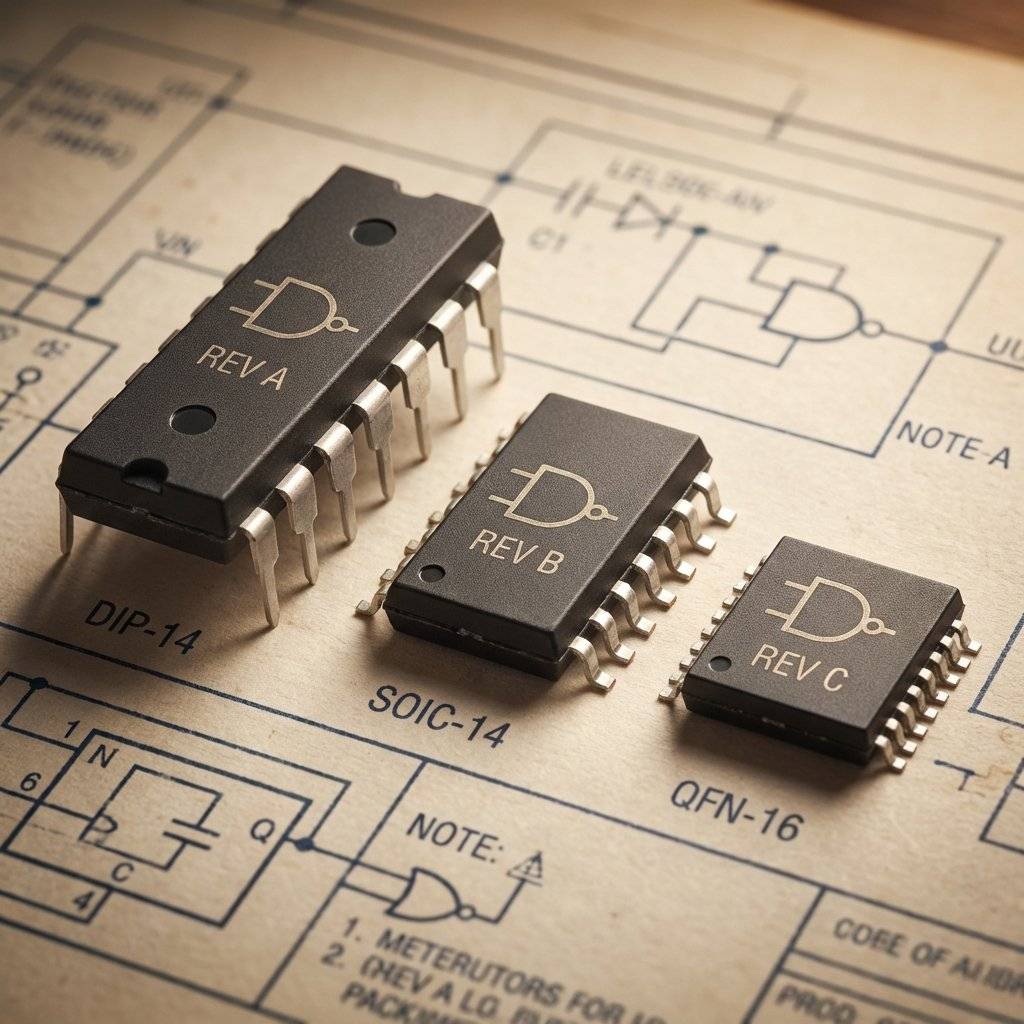
Have you noticed parts like NE555P vs NE555N?
The letters at the end are the Metadata.
It’s like looking at a version tag: v1.2.3-beta-production.
The core logic is the same, but the “Environment Config” is different.
Don’t just Google “NE555 Datasheet.”
You’ll get 1,000 spammy sites trying to sell you dubious PDFs or malware.
As a professional, use these “Search Engines for Hardware”:

You don’t read a datasheet front-to-back.
You “Scout” it.
Go find the datasheet for the 74HC595 Shift Register. Try to find:
reset() method).If you can find those three things, you are officially a “Datasheet Reader.”
| Symbol | Name | What it means in Software |
|---|---|---|
| Supply Voltage | The API Endpoint URL | |
| Ground | The null space / Return path | |
| Milliamps / Microamps | Data bandwidth / Flow rate | |
| Nano / Micro seconds | Latency / Timeout values | |
| Pico / Micro farads | Buffer size / Cache capacity | |
| Resistance | Firewall / Bandwidth throttle |
| Abbreviation | Expanded Name | Software Context |
|---|---|---|
| ESD | Electrostatic Discharge | Kernel Panic (Static electricity) |
| EMI | Electromagnetic Interference | Cross-thread noise / Race conditions |
| RoHS | Restriction of Hazardous Substances | License Compliance |
| MSL | Moisture Sensitivity Level | Storage/Environment config |
| MTBF | Mean Time Between Failures | Uptime SLA |
| PDIP | Plastic Dual In-line Package | Standard Dev Distribution |
| LDO | Low Dropout Regulator | Efficiency Middleware |
In the 1970s, engineers had literal bookshelves of “Data Books.”
If you wanted to know the spec for a transistor, you had to flip through a physical index.
Today, we have searchable PDFs.
But the structure remains the same because the physical laws haven’t changed.
Datasheets often mention ESD Protection.
Human beings are giant capacitors.
If you touch a chip without being grounded, you can release to .
This is the hardware equivalent of a SQL Injection.
One stray spark bypasses all your logic and destroys the internal components.
The datasheet tells you how many the chip can withstand before it “Crashes” permanently.

Sometimes the datasheet is too brief.
Manufacturers also publish Application Notes.
These are the “Tutorials” and “Whitepapers” of hardware.
If the datasheet is the API documentation, the Application Note is the “Advanced Integration Guide.”
You find them linked at the bottom of the product page.
If you are building something complex (like an audio amplifier), the Application Note will save you weeks of trial and error.
Reading a datasheet isn’t about memorizing numbers.
It’s about Empowerment.
When you stop guessing and start reading, you move from a “Trial and Error” tinkerer to an Engineer.
You gain the confidence to buy a $0.10 chip and know exactly how it will behave.
Never skip the footnotes.
The footnotes are the “Stack Overflow” comments of the datasheet.
They contain the caveats:
These footnotes are where the “Magic Smoke” usually escapes from.
If you miss a required decoupling capacitor mentioned in a tiny asterisk at the bottom of page 42, your circuit will be unstable.
You’ll spend three days debugging “Phantom Bugs” that are actually just electrical noise.
The next time you’re stuck, don’t just Google for a tutorial.
Download the PDF.
Find the table.
Read the fine print.
The answer is always there, buried in a footnote on page 67.
Welcome back to the source code of reality.
Don’t let the paperwork stand between you and your creation.
Embrace the PDF.
Conquer the constraints.
Build something beautiful. Terminology Cheat Sheet for Developers
| DataSheet Term | Developer Equivalent |
|---|---|
| Typical Value | Default Case / Average Case |
| Absolute Max | Hard Crash Boundary |
| Pinout | API Declaration / Class Interface |
| Timing Diagram | Async Flow / Race Condition |
| Package | Distribution Format / Deployment Bundle |
| Quiescent Current | Idle CPU Usage / Sleep Power |
| Propagation Delay | Network Latency / Execution Time |

Stop burning out your LEDs. Master electrical resistance, Ohm's Law calculations, and build your first protected circuit in Day 3 of our Electronics series.
Read More →
Understand electrical current like a pro. From drift velocity to safety, master the flow of electrons in Day 2 of our Analog Electronics series.
Read More →
Demystify voltage once and for all. Explore the physics, history, and practical measurement of electrical potential in this deep-dive guide for analog electronics beginners.
Read More →