The Great Restrictor: Mastering Resistance & Ohm's Law
Stop burning out your LEDs. Master electrical resistance, Ohm's Law calculations, and build your first protected circuit in Day 3 of our Electronics series.
Read More →
* SYSTEM.NOTICE: Affiliate links support continued laboratory research.
Welcome back to the edge of the silicon.
In our previous session, we discussed the philosophical leap from moving bits to moving atoms. If you’re here, it means you’ve survived the existential crisis of realizing your code has been living in a headless cloud server, and you’re ready to see it manifest in the physical world.
In the software world, our first ritual is print("Hello, World!"). It’s the smoke test. If that string appears in the terminal, the environment is configured, the compiler is happy, and the laws of logic are intact.
In hardware, our “Hello World” is the Blink. Specifically, making a physical Light Emitting Diode (LED) glow under the command of a circuit. It sounds simple—borderline trivial—until you realize that unlike a print statement, a circuit can actually catch fire if you mess up the syntax.
Today, we are going to build that circuit. We will decode the physical “API” of electronic components, understand the “runtime” of physics, and move our first electron with intent.
Before we write any “code” (build the circuit), we need to import our libraries. In electronics, libraries are physical objects. For this project, you need the following “dependencies”:
As a developer, you understand memory addresses. A breadboard is essentially a physical grid where certain “addresses” (holes) are hard-wired together. If you don’t understand how these holes are connected, you are essentially writing to random memory locations—nothing will work, and you might cause a collision.
Think of the breadboard as having two distinct “memory regions”:

Pro-Tip for Devs: The center trench is designed so that Integrated Circuits (ICs) can straddle it, ensuring that the pins on the left don’t “short-circuit” with the pins on the right. It’s like a namespace separation for physical pins.
As a developer, you might wonder if there’s a performance penalty to using a breadboard. In high-frequency electronics, there is. Because the metal clips are parallel to each other and separated by plastic (a dielectric), they form tiny Parasitic Capacitors.
For our Blink project (running at ), this is irrelevant.
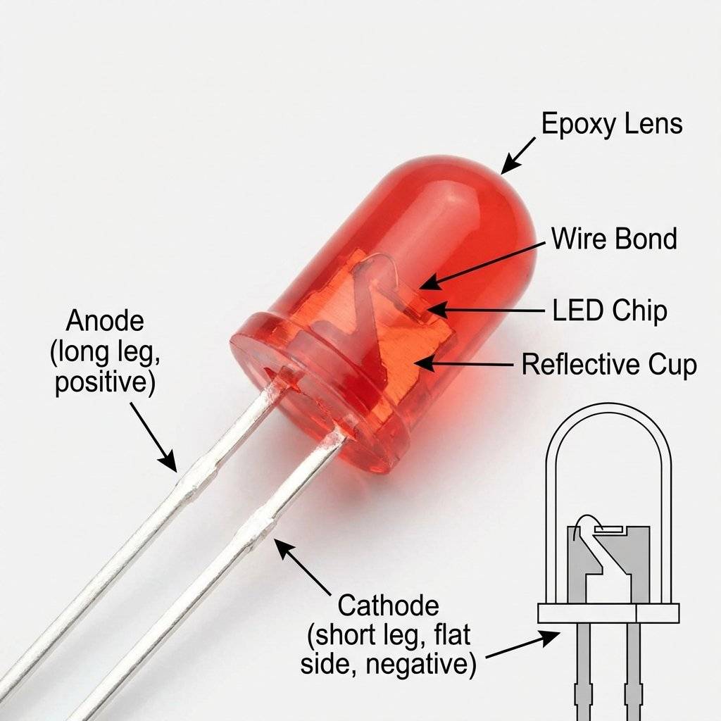
The Light Emitting Diode (LED) is a delightful little component. In software terms, it’s a Write-Only Boolean Output.
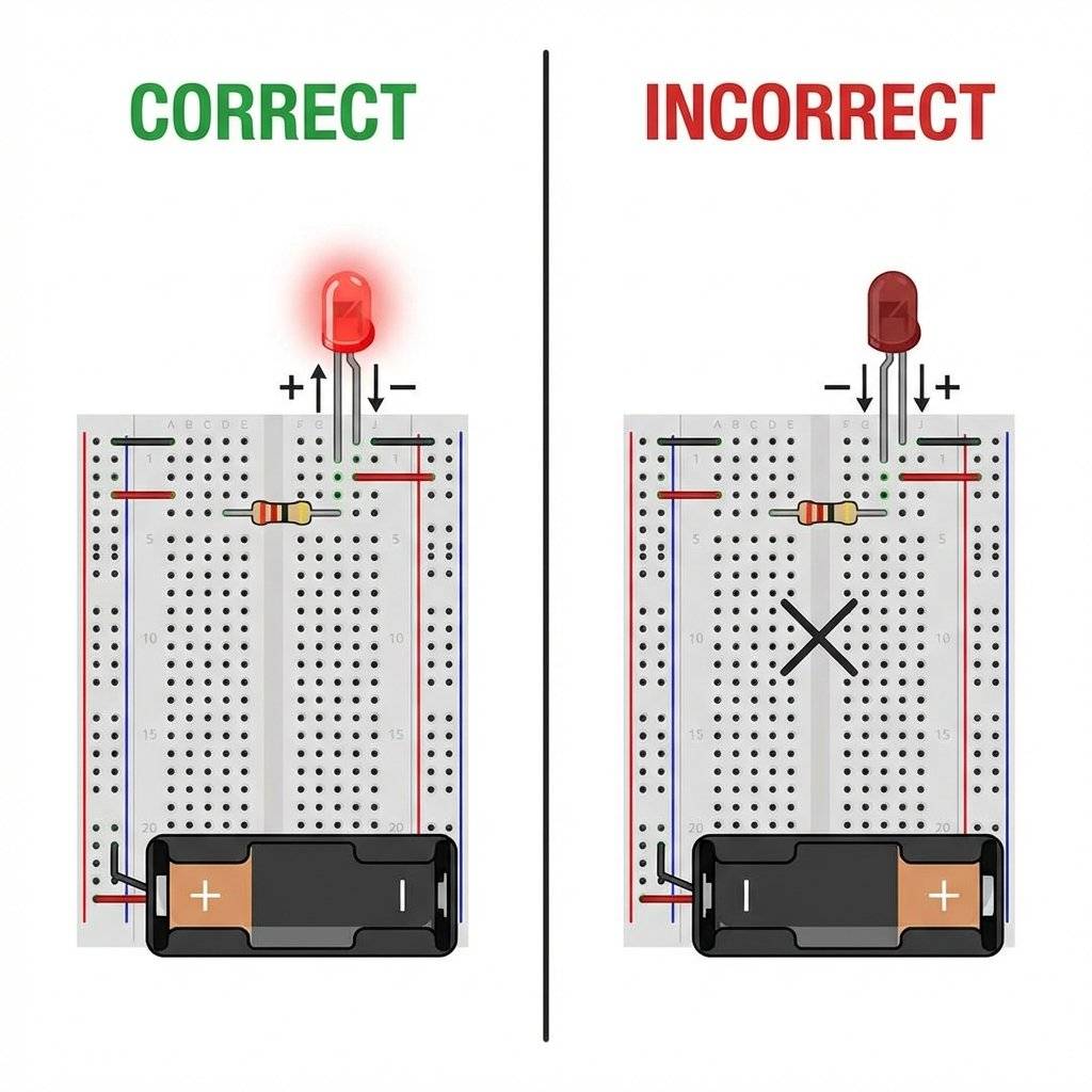
However, unlike a software boolean, the LED is a Diode. This means it is a one-way street for electricity. If you plug it in backward, the circuit is physically broken (infinite resistance). It won’t break anything, but it won’t light up either.
In your IDE, the compiler tells you if your syntax is wrong. The LED tells you through its physical shape:
Before 1971, if you wanted to prototype a circuit, you practiced “Point-to-Point Wiring.” This involved wrapping wires around terminal strips or soldering components directly to each other in a messy, fragile nest known as “dead bug style.” It was the equivalent of writing code in machine hex without an assembler.
The modern “Solderless Breadboard” was patented by Ronald J. Portugal in 1971. His innovation was the internal spring clip—specifically, the way it could grip components of varying thickness without losing its “springiness.” For us, it’s the ultimate IDE for atoms: instant feedback, no permanent mistakes, and a clear grid for logical organization.
As a dev, you’re used to different data types having different memory footprints. In hardware, different LED colors have different “forward voltages” ().
To create a photon, an electron must “jump” across a gap between energy levels. The size of this gap determines the color (frequency) of the light.
Why does this matter? Because if you swap a Red LED for a Blue one on the same resistor, the Blue one might be significantly dimmer (or not light up at all) because it requires more “Pressure” to initiate the energy jump. This is the hardware equivalent of a function having different resource overheads based on its parameters.
This is where many developers get confused. In software, if we want a loop to run slower, we add a sleep(). In hardware, if we want to prevent a component from drawing too much current and exploding, we add a Resistor.
An LED behaves like a “Negative Resistance” component once it starts conducting. If you connect it directly to 5V, it will try to draw an infinite amount of current. For a few milliseconds, it will be the brightest light in the room. Then, the silicon junction will reach its thermal limit, the wire bond will melt, and you get—you guessed it—Magic Smoke.
The Resistor is your Rate Limiter. It enforces a physical constraint on the flow of electrons, keeping the current within the LED’s “Safe Operating Area” (SOA), which is usually around ( Amps).
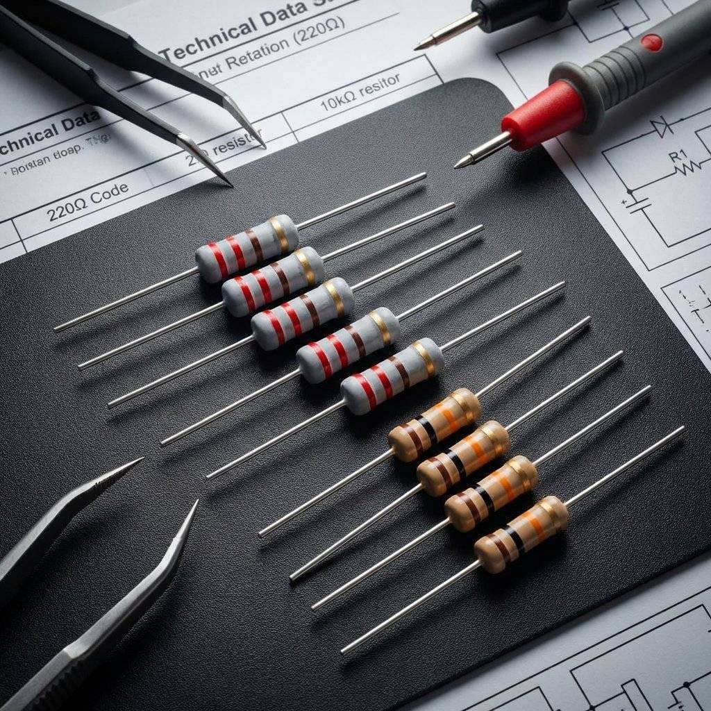
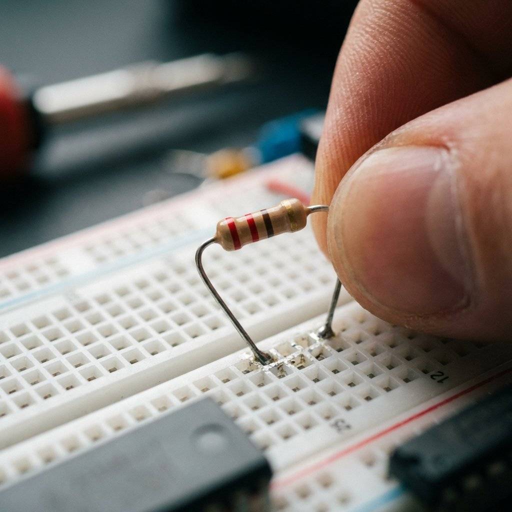
Resistors don’t have numbers printed on them (unless they are tiny SMD ones). They use a color-coding system.
The first two bands are digits, the third is the multiplier (10 to the power of X), and the fourth is the tolerance (how much the “compiler” can deviate from the specification). is our target for this “Hello World” because it’s the standard safest value for almost any LED on a logic rail.
| Band Color | Digit Value | Multiplier |
|---|---|---|
| Black | 0 | (1) |
| Brown | 1 | (10) |
| Red | 2 | (100) |
| Orange | 3 | (1,000) |
| Yellow | 4 | (10,000) |
| Green | 5 | (100,000) |
| Blue | 6 | (1,000,000) |
For our Red-Red-Brown resistor: (Red) (Red) (Brown) = .
We use the foundational equation of the universe: . To calculate the perfect resistor, you subtract the LED’s consumption from the source:
Equation: Calculation:
Worked Example for 3.3V Systems (Raspberry Pi/ESP32): Notice how the requirements change based on the “Runtime Environment” (Voltage). We use because is the absolute minimum for ; gives us a “Safety Buffer” of roughly 50%, ensuring your hardware never crashes (burns out) even if the rail spikes.
| Symptom | Probable Cause | Fix |
|---|---|---|
| LED is DARK | Polarity reversed | Flip the LED legs. |
| LED is DARK | Open circuit | Check for loose wires in the breadboard. |
| LED is DARK | Power source off | Ensure Arduino USB is plugged in. |
| LED is DIM | Resistor too high | Swap for . |
| LED popped once | Resistor missing | LED is fried. Replace it and add a resistor. |
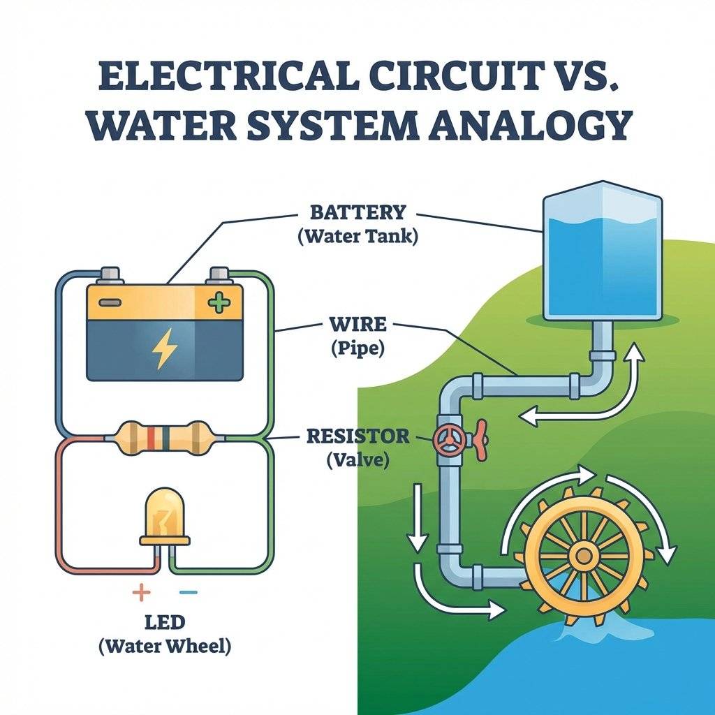
If you find Voltage and Current abstract, use the Water Analogy. It is the “Mental Model” that every engineer uses under the hood.
If you have high pressure but a wide-open pipe (Zero Resistance), you get a flood. In electronics, this is a Short Circuit, and it’s the hardware equivalent of a memory leak that consumes all system resources until the OS (Power Supply) shuts down or the hardware melts.
In code, we care about indentations and naming conventions. In hardware, we care about Wire Management.
Let’s build. We are going to use the Arduino as a 5V “Base Station” or Power Supply. We aren’t even going to write code yet; we are just going to build a “Raw” Hardware Hello World to prove the physics.
GND pin on the Arduino to the Blue/Black rail on the breadboard. In electronics, Ground is your reference point—everything is measured against it.5V pin on the Arduino to the Red rail on the breadboard.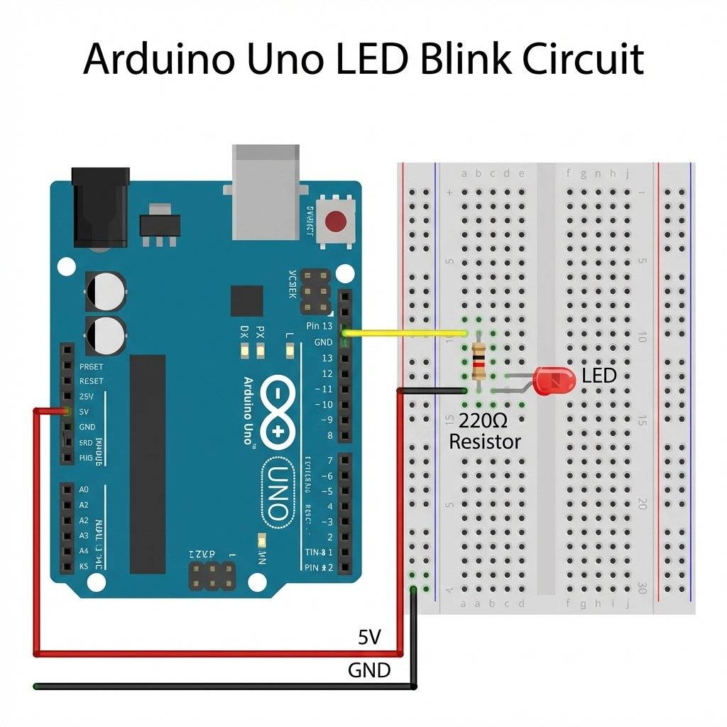
Once that last jumper wire hits the Ground rail, the LED should glow immediately. You have closed the loop. You have manifested a logical True (5V → GND) in the physical world.
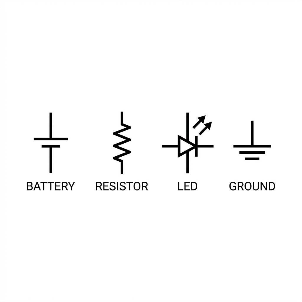
As you progress, you’ll stop looking at photos of breadboards and start looking at Schematics. This is the “Pseudo-code” of electronics. It ignores the physical location of components and focuses entirely on the logical connections.
In software, stderr tells you what happened. In hardware, a “bug” usually manifests as an LED that refuses to light up. Here is how to debug like a Pro:
If your LED is backward, it blocks current entirely. It’s essentially an if(false) block that never executes. Flip the LED legs in the breadboard.
Are two of your components touching that shouldn’t be? If the two legs of your resistor touch each other, the electricity will take the “short path” around the resistance, likely blowing the LED. This is a Short Circuit.
Ensure your power wires (Red and Black) are in the correct pins on the Arduino. Many beginners accidentally plug the 5V line into the AREF pin or Vin. Your circuit needs exactly and a common Ground.
If your LED is flickering randomly, you might have a loose connection. The breadboard uses internal metal clips; if they are worn out, the connection is intermittent. This is the hardware equivalent of a “Flaky Test.”
In software, we rely on Time Travel Debugging and Stack Traces. In hardware, you only have the Present State.
Everything in hardware is concurrent. Electrons don’t wait for your next line of code unless you’ve implemented a clock. When you debug a circuit, you are looking for Continuity and Potential. If a wire is loose, it’s not a syntax error—it’s a physical interruption of the runtime environment.
If you want to “Inspect Element” on your physical circuit, you need a Multimeter. Set it to 20V DC.

One of the most common rookie mistakes is the “Short Circuit through the Meter.” When measuring voltage, your meter is a high-impedance device (it doesn’t affect the circuit). But when you measure Current (Amps), the meter becomes a wire (Zero Resistance). If you accidentally leave your probes in the “A” or “mA” jack and try to measure voltage across the 5V rail, you will bridge 5V to GND directly through your meter.
If a standard LED is a boolean, an RGB LED is a struct or a Color object. It contains three separate LED dies (Red, Green, Blue) inside a single plastic package.
color: rgb(255, 0, 128);.In our future projects, we will use these to create status indicators that change based on system health—just like your IDE’s task bar or a build server’s status light.
In software, things happen because a CPU executed an instruction. In hardware, things happen because Physics exists.
If you have a 5V source and a path to Ground, electricity will move. It’s like a script that is constantly running in a while(true) loop at the speed of light. You don’t “call” a circuit; you “enable” a path. Understanding that your components are constantly interacting with the environment (temperature, EMI, resistance) is the first step to becoming a senior hardware engineer.
If your circuit works but the light is barely visible, check these “Config Settings”:
pinMode(X, OUTPUT)? Without this, the pin is in “High Impedance” mode—like a variable that hasn’t been initialized.Right now, our LED is just “Hardcoded” to Always-On. To make it smart, we need the Arduino to act as our Processor.
Inside the Arduino chip (the ATmega328P), there is a register called PORTB. When we connect our circuit to Pin 13 instead of the 5V rail, we give our software control over that 5V supply through a transistor-based “Switch.”
/**
 * Project: Hardware Hello World (Part 2)
 * Series: The Software Developer's Hardware Journey
 * Description: Toggling a physical bit to control an LED.
 */

// We define our 'Pin Address' as a constant
// In the Arduino runtime, Pin 13 is the internal LED pin.
const int LED_PIN = 13;

void setup() {
  // Configures the logic gate for Output mode.
  // This tells the silicon to actively DRIVE the pin.
  // Without this, the pin defaults to INPUT (tri-state).
  pinMode(LED_PIN, OUTPUT);
}

void loop() {
  // SET_BIT(PORTB, 5) - Set the pin to 5V (Logical True)
  digitalWrite(LED_PIN, HIGH);
  delay(1000); // Wait 1 second

  // CLEAR_BIT(PORTB, 5) - Set the pin to 0V (Logical False)
  digitalWrite(LED_PIN, LOW);
  delay(1000); // Wait 1 second
}As a software developer, your most expensive asset is your laptop. When you plug an Arduino into your USB port, you are creating a physical bridge between your 5 breadboard.
Most USB 2.0 ports are limited to .
If you’re serious about this journey, get a Powered USB Hub. It acts as a “Sandbox” for your power rails. If your circuit shorts out, the hub will likely shut down or sacrifice its own fuse, protecting your laptop’s motherboard.
In the early days of electronics, was the absolute standard (TTL Logic). Today, modern chips (like the ESP32 or the Raspberry Pi) operate at or even .
Warning for Devs: If you apply 5V to a 3.3V pin (like on a Raspberry Pi), you will permanently “fry” the silicon. There is no try/catch for overvoltage. Always check the “Datasheet” (the API documentation for chips) before plugging in.
You’ve successfully build a circuit that reacts to a static input. But real hardware projects are interactive. Here is where the journey goes next:
Q: Can I use any resistor? A: No. Too low and the LED dies. Too high and the LED stays dark. to is the “Goldilocks Zone” for 5V systems.
Q: Why does the breadboard have two sets of rails? A: Convenience. One set for the top of your circuit, one for the bottom. They are not connected unless you “bridge” them with jumper wires.
Q: Is dangerous? A: No. You cannot be electrocuted by DC. Your skin resistance is high enough that you won’t even feel it. However, it can damage sensitive electronics or cause a battery to heat up if shorted.
There is a specific feeling—a distinct “ping” in the brain—when you see that LED flash for the first time. It is deeper than the feeling of a successful deployment or a passing test suite. It is the realization that you have successfully built a circuit that reacts to a static input. It is the realization that you have successfully negotiated with the fundamental forces of physics to execute your logic.
You aren’t just a coder anymore. You are an Engineer of Atoms. You are no longer confined to the screen.
In the next post, we’re going to look at the Hardware Debugger’s Toolkit. We’ll talk about why the Multimeter is your new IDE, how to decode datasheets without losing your mind, and how to spot a “Cold Solder Joint” from across the room.
Until then, keep your resistors high and your currents low.
Welcome to the real world. Let’s make something glow.


Stop burning out your LEDs. Master electrical resistance, Ohm's Law calculations, and build your first protected circuit in Day 3 of our Electronics series.
Read More →
Understand electrical current like a pro. From drift velocity to safety, master the flow of electrons in Day 2 of our Analog Electronics series.
Read More →
Demystify voltage once and for all. Explore the physics, history, and practical measurement of electrical potential in this deep-dive guide for analog electronics beginners.
Read More →