Time Travel: How to Build a Precision Digital Clock with Arduino & DS3231
Stop using delay() for time! Learn to master the DS3231 Real Time Clock (RTC), I2C protocol, and CR2032 battery backups to keep precise time for years.
Read More →
* SYSTEM.NOTICE: Affiliate links support continued laboratory research.
Welcome to Day 5. We have covered Resistors (Friction), Capacitors (Buckets), and Transistors (Valves). Now, we combine them all into a single black box. Meet the Integrated Circuit (IC). Specifically, the NE555 Timer.
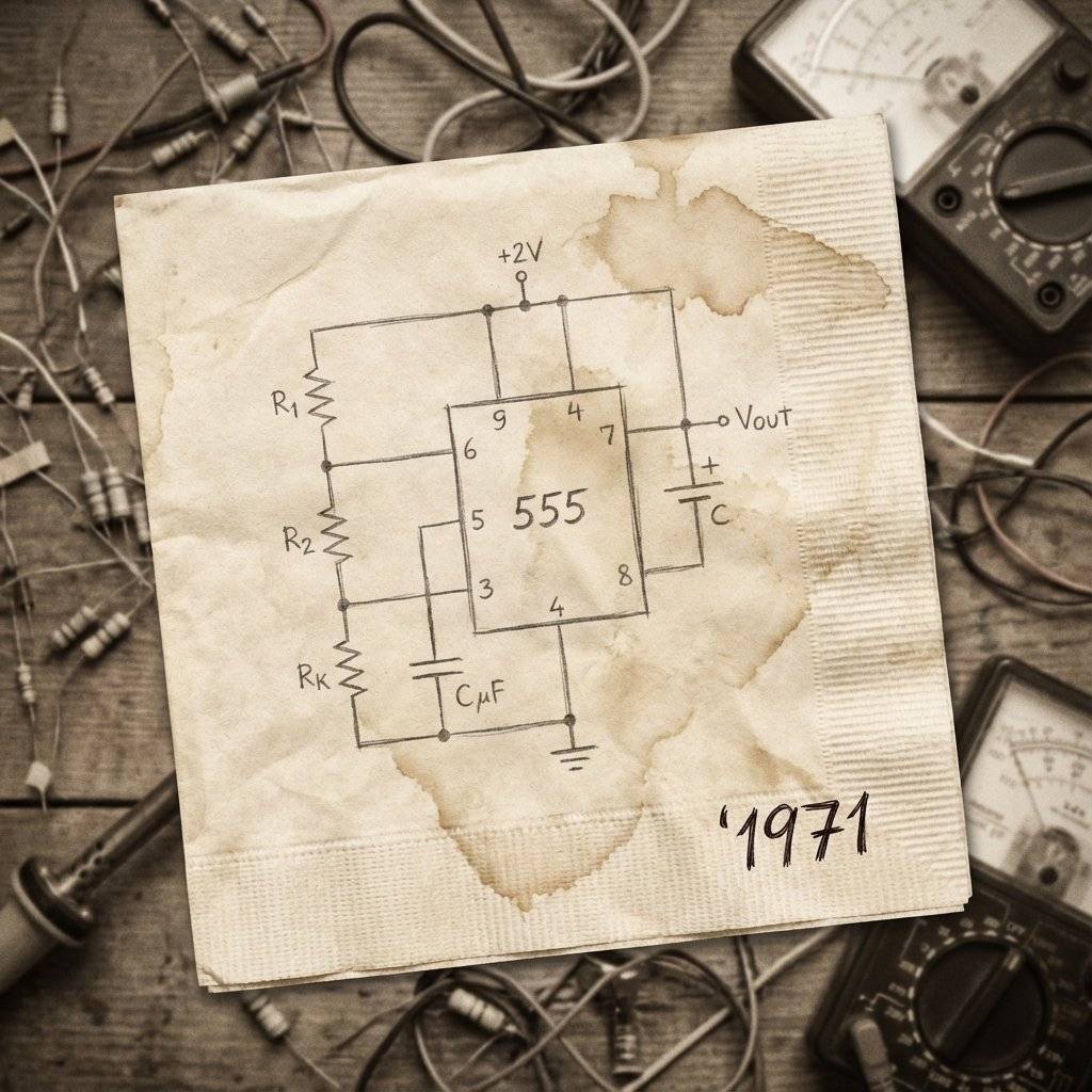
Invented in 1971 by Hans Camenzind, it is the most popular chip in history. Billions are made every year. Why? Because it does one thing perfectly: It counts time.
Why is it called the “555”? Open it up (microscopically), and you will find three resistors connected in series. This creates a “Voltage Divider” that splits the power into 1/3 and 2/3 chunks. This is the reference ruler the chip uses to measure the voltage filling up a capacitor.
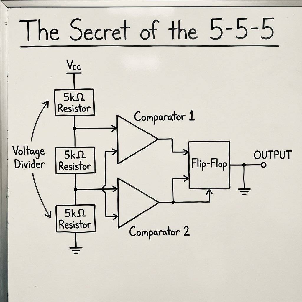
It’s not magic. It’s logic. The 555 contains:
Comparator 1 (Threshold): Checks if voltage is > 2/3 Vcc.
Comparator 2 (Trigger): Checks if voltage is < 1/3 Vcc.
One SR Flip-Flop: This is the “Memory”.
When the “Start” eye sees low voltage, it SETS the memory (Output High).
When the “Stop” eye sees high voltage, it RESETS the memory (Output Low).
One Transistor (Discharge): This is the “Drain”.
When the memory is Reset (Low), this transistor turns ON and shorts Pin 7 to ground, emptying the capacitor.
This beautiful dance of analog sensing (Comparators) and digital memory (Flip-Flop) is what makes the 555 so versatile.
It has 8 legs. If you hold the chip with the notch/dot up, pin 1 is top-left. Wait, no! Pin 1 is bottom-left (counter-clockwise numbering). Let’s look at the map.
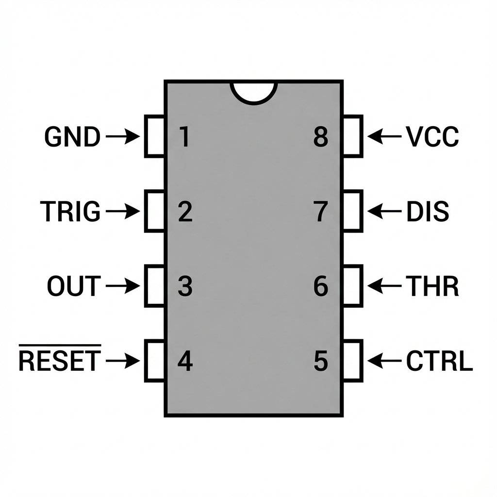
GND (Ground): The negative battery terminal.
TRIG (Trigger): The “Start” button. A low voltage here starts the timing.
OUT (Output): Where the action happens. Turns your LED On/Off.
RESET: An emergency stop button. Usually connected to +Vcc to prevent accidental resets.
CTRL (Control): Advanced tuning leg. Usually ignored (connected to ground via a small capacitor).
THR (Threshold): The “Stop” button. Checks if the capacitor is full.
DIS (Discharge): The Drain. Empties the capacitor to restart the cycle.
Vcc (Power): The positive battery terminal (—).
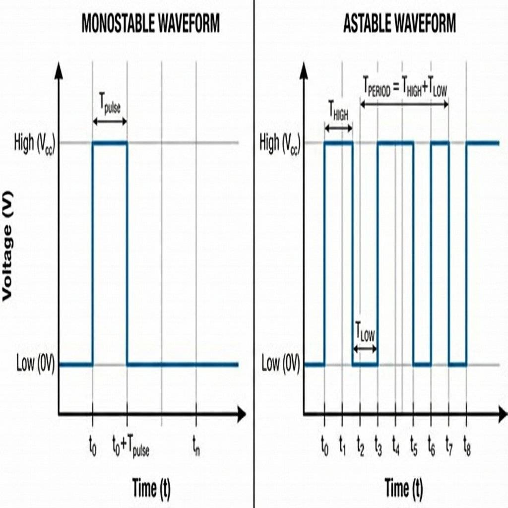
The 555 has two main moods.
Mono = One. Stable = State.
Behavior: It sits quietly (Off). You press a button. It turns ON for a specific time (say, 5 seconds), then turns OFF and waits again.
Analogy: A toaster. You push the lever, it heats for 2 mins, then pops.
Uses: Motion sensor lights, auto-shutoff circuits.
A = Not. Stable = No fixed state.
Behavior: It never rests. It flips On, Off, On, Off… forever.
Analogy: Your turn signal indicator.
Uses: LED flashers, clocks, tone generators, PWM motor controllers.
We learned the Astable math (Frequency). But what about the “One-Shot” timer? How long does the toaster stay on? The formula is simpler: Time (T) = 1.1 * R * C
Let’s try it.
R: ()
C: ()
Want ()? Use a capacitor and calculate R. (So, use a or a Potentiometer).
Before you start, gather these parts.
| Component | Value | Quantity | Notes |
|---|---|---|---|
| IC | NE555 | 1 | The star of the show. |
| Resistor | 1 | Brown-Black-Red. | |
| Resistor | 1 | Brown-Black-Orange. | |
| Capacitor | 1 | Electrolytic (Watch polarity!). | |
| Capacitor | 1 | Ceramic (For Pin 5). | |
| LED | Red | 1 | Or Blue/Green. |
| Resistor | 1 | For LED protection. | |
| Battery | 1 | High voltage is fun. |
Does your circuit turn on randomly? The Trigger Pin (Pin 2) is ultra-sensitive. If you leave a long wire attached to it without connecting it to anything, it acts as an Antenna. It picks up electromagnetic noise from the lights in your room, your phone, or even static from your shirt. The Fix: Use a “Pull-Up Resistor”. Connect a resistor from Pin 2 to Positive (). This keeps the pin “High” (Off) until you explicitly force it “Low” (On).
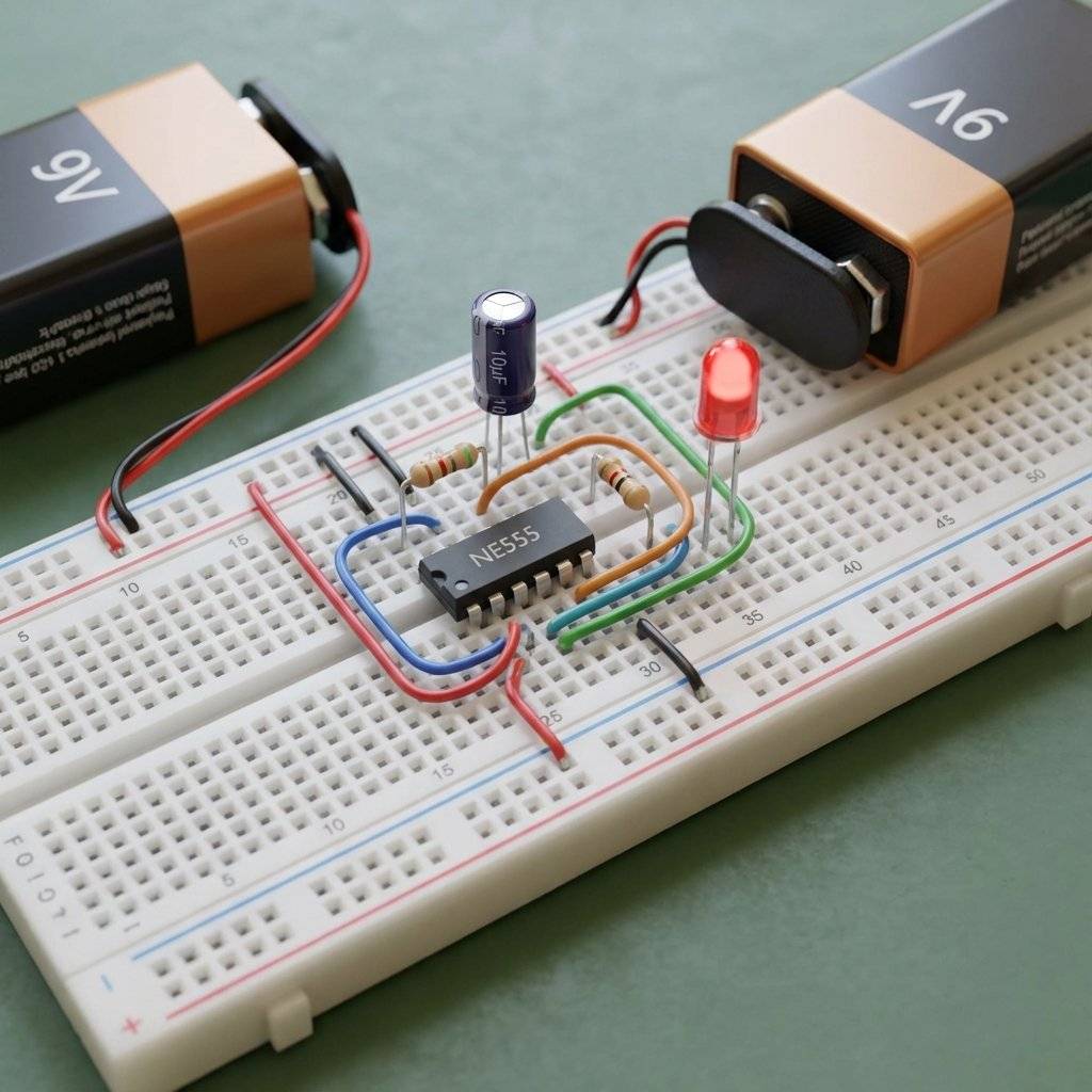
We are going to build the Astable Mode. We want an LED to flash automatically. For this, we need:
R1 ()
R2 ()
C1 ( capacitor)
NE555 Chip
It looks messy on a schematic, but follow the logic:
The Capacitor C1 fills up through R1 + R2.
When it’s 2/3 full, pin 6 (Threshold) says “Stop!”.
Pin 7 (Discharge) opens a drain.
The Capacitor empties through R2 only.
When it’s 1/3 full, pin 2 (Trigger) says “Start!”.
Repeat forever.
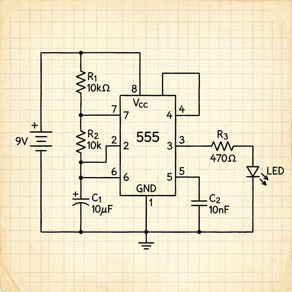
Pin 1: To Blue Rail (-).
Pin 8: To Red Rail (+).
Pin 4: To Red Rail (+) (Don’t reset!).
Pin 2 & 6: Connect them together with a wire bridge.
C1: Positive leg to Pin 2/6, Negative leg to Ground.
R1: From +Vcc to Pin 7.
R2: From Pin 7 to Pin 2/6.
Output: LED + Resistor connected to Pin 3.
How fast does it blink? The speed (Frequency) depends on how fast the bucket (C1) fills through the pipes (R1, R2).
:
:
: ()
(Blinks about 7 times per second).
Want it slower? Use a bigger Capacitor (100µF). Want it faster? Use a smaller Resistor (R2).
Frequency isn’t the whole story.
(Time On):
(Time Off):
Total Period ():
Notice something? uses , while only uses . This means with a standard 555 circuit, you can never have a Duty Cycle less than 50% (On time is always > Off time). To cheat this, you need to add a Diode across R2 to bypass it during charging.
Working with chips is different than working with big resistors.
Chip Extractor: A U-shaped tool to pull the chip out without bending pins.
Logic Probe: A pen that lights up “Red” for High and “Green” for Low. Perfect for debugging digital logic.
Needle Nose Pliers: For straightening those bent pins (it happens to everyone).
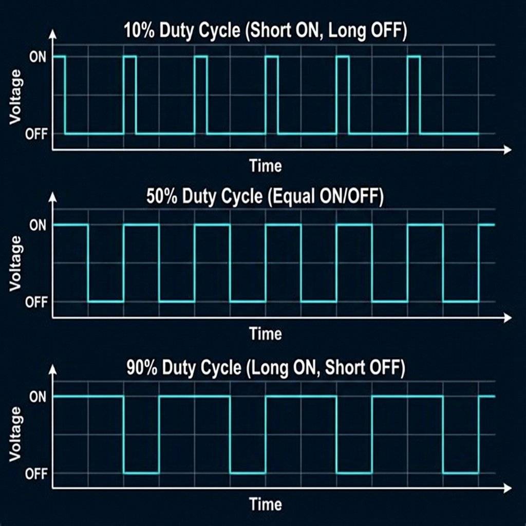
What if we want to dim an LED using a 555? We don’t lower the voltage. We turn it On and Off really fast.
10% Duty Cycle: On for , Off for . (Dim).
90% Duty Cycle: On for , Off for . (Bright).
This is how cordless drills control speed. They use a 555 (or microcontroller) to chop the battery power thousands of times a second.
You know those little motors in RC planes? They use PWM.
By carefully tuning R1, R2, and C1 on a 555 Timer, you can build a knob that sweeps a servo arm back and forth without using a single line of code or a microcontroller. This is pure analog control.
If you dissolved the black plastic with acid, you would see a tiny city of silicon. Transistors, resistors, and capacitors etched onto a crystal wafer. It’s art.

You might think digital computers killed the 555. You are wrong.
Toasters: The browning darkness knob? It’s a Variable Resistor changing the time constant of a 555 (Monostable mode).
Microwaves: The “Defrost” cycle that turns the magnetron On and Off? That’s a slow Astable 555.
Wiper Blades: The “Intermittent” setting on your car wipers.
Toys: Every blinking LED sword or noise-making gun likely has a 555 (or a cheap knockoff) inside.
It is cheaper, tougher, and simpler than a microcontroller for these basic jobs.
Hans Camenzind designed the 555 in 1970 while working as a freelancer. He almost didn’t make it. Engineers at Signetics argued it was unnecessary. He drew the first layout on a large sheet of paper (rubylith) by hand. It launched at $0.75. Today, you can find them for as little as $0.05 in bulk. It is the only chip from the 70s that is still in every electronics store today.
IC (Integrated Circuit): A silicon chip containing microscopic components.
DIP (Dual Inline Package): The standard “Bug” shape with legs on both sides.
Duty Cycle: The percentage of time a signal is “ON” vs “OFF”.
Comparator: A circuit that compares two voltages and outputs High or Low.
Flip-Flop: A digital memory cell that stores 1 bit (High or Low).
One-Shot: Another name for Monostable mode.
Potentiometer: A variable resistor (knob).
BOM (Bill of Materials): The shopping list for a project.
The 555 is famous for being “noisy”. When it switches its output, it draws a huge spike of current. This can make the voltage on your breadboard dip, causing the chip to reset itself. The Fix: Always put a 100µF Capacitor and a 0.1µF Capacitor right next to Pin 1 and Pin 8. This is called “Bypassing”. It acts as a local energy reserve for the chip. If your circuit acts weird, add more capacitors.
Not all 555s are equal.
NE555 (Bipolar): The classic. Power hungry. Output goes to below . Needs .
LMC555 / TLC555 (CMOS): The modern version. Low power. Output goes rail-to-rail ( to ). Works on . If you are running on a coin cell battery, use the CMOS version. If you are driving a loud buzzer, use the Bipolar version.
Don’t want to do the math? Here are common values for R1=1k, R2=10k.
| Capacitor (C1) | Frequency (approx) | Behavior |
|---|---|---|
| Slow blink (Car signal) | ||
| Fast blink (Strobe) | ||
| Hum (Low bass) | ||
| Beep (Alarm clock) | ||
| High whine (Mosquito) |
You have now built a machine that experiences “Time”. Before today, your circuits were instantaneous. You pushed a button, the light turned on. Now, your circuit has a schedule. It waits. It pulses. It counts. This is the fundamental difference between “State” (Static) and “Behavior” (Dynamic). The 555 Timer is the first step towards building a robot brain. It is the metronome that keeps the orchestra of electrons playing in sync.
| Component/Mode | Function |
|---|---|
| Pin 1 | Ground (GND). |
| Pin 3 | Output (Signal). |
| Vcc | Power (Up to ). |
| Monostable | One-shot (Timer). |
| Astable | Continuous (Blinker/Clock). |
| Frequency | Controlled by , and . |
Check Pin 4 (Reset). Is it connected to +Vcc? If it’s floating or grounded, the chip is held in reset.
Check your Capacitor. Is it backwards? Is Pin 6 connected to Pin 2?
Did you connect Pin 3 (Output) directly to Ground or Vcc? Use a resistor!
The 555 Timer relies heavily on the Capacitor (C1) to keep time. But capacitors are imperfect.
Tolerance: A “100µF” capacitor might actually be 80µF or 120µF. This means your 60-second timer might actually be 48 seconds or 72 seconds. Precision timing requires expensive Tantalum capacitors.
Leakage: Cheap electrolytic capacitors “leak” current internally. If you try to make a timer that lasts for hours, the leakage might be faster than the filling rate, and the timer will never finish!
Polarity: They have a Grey Stripe (-). If you plug them in backwards, they boil and pop.
The NE555 is tough, but it has one weakness: Reverse Voltage. If you accidentally touch the Battery (+) to the Ground Pin (1) and Battery (-) to the Vcc Pin (8), the chip is dead instantly. There is no protection. Always double-check your power rails before plugging in the battery.
You have built a blinker. Now build a Traffic Light. Goal:
Red LED stays on for 3 seconds.
Yellow LED stays on for 1 second.
Green LED stays on for 3 seconds.
Loop.
Hint: You might need multiple 555 timers chained together (one triggering the next), or a 555 timer driving a Counter Chip (like the 4017). We will cover the 4017 Decade Counter later, but if you can figure it out now, you are ahead of the class.
In an era of 3GHz processors and AI chips, why use a 50-year-old timer? Because it is Atomic. It represents a fundamental unit of logic: “Do X for Y seconds.” It doesn’t need to boot up. It doesn’t crash. It doesn’t need firmware updates. It just works. As long as humans need to blink lights and beep buzzers, the 555 will exist.
The Variable Speed: Replace R2 with a Potentiometer (Variable Resistor). Now you can tune the blink speed by turning a knob!
The Tone Generator: Replace the LED with a small Speaker (and use a small Capacitor like 0.1µF). You just made an annoying alarm buzzer!
Blinking LEDs is visual. Let’s get audible. The 555 can vibrate a speaker at audio frequencies (—). By changing the resistance () instantly, we change the pitch.
Build standard Astable circuit.
Replace R2 with a chain of resistors (e.g., , , ) in series.
Add push buttons between the junctions of these resistors and Pin 7.
Press Button 1 -> Short path (Low resistance) -> High Pitch.
Press Button 3 -> Long path (High resistance) -> Low Pitch.
Connect a small speaker + capacitor to Pin 3.
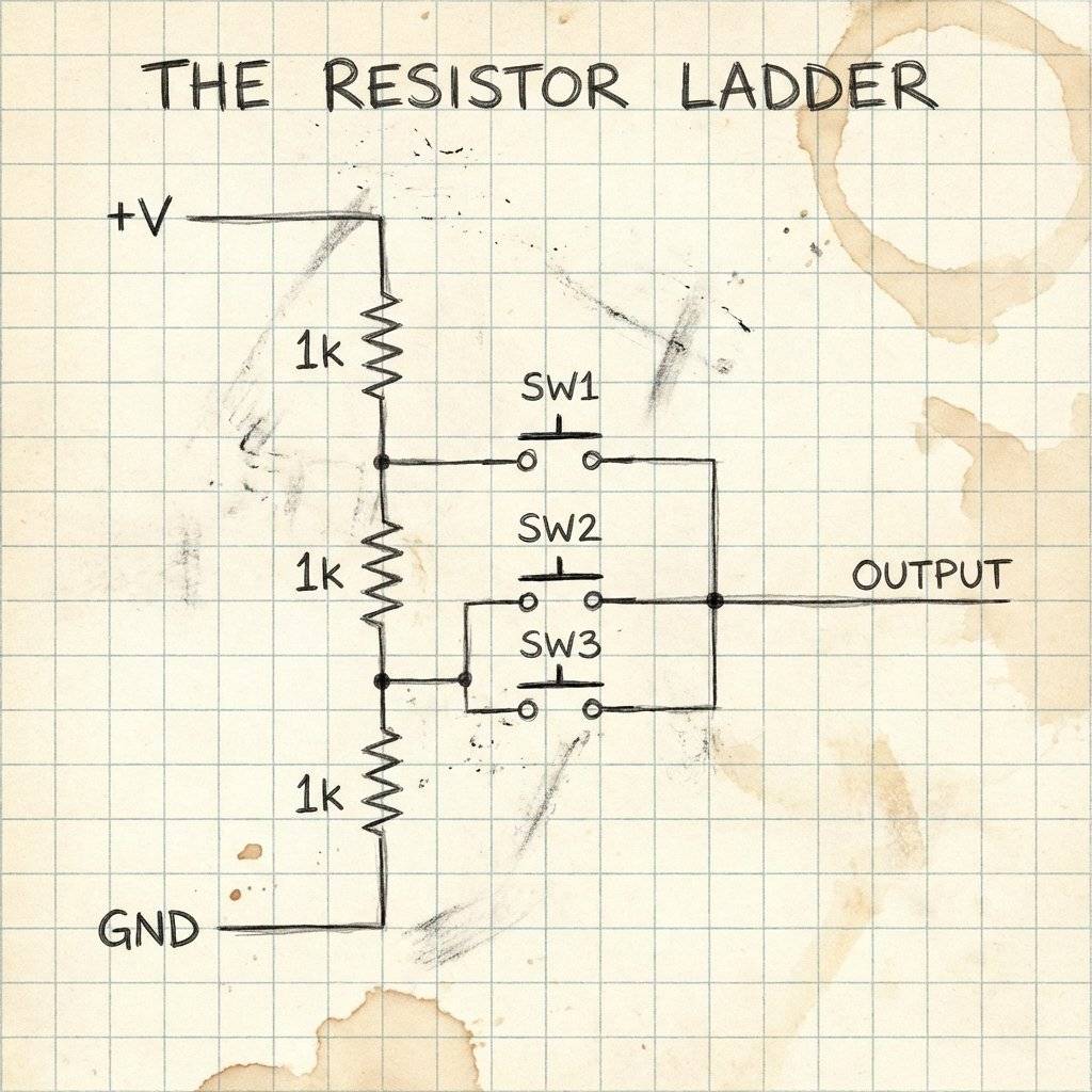
You just built a crude synthesizer. The first musical keyboards used exactly this principle (dividing voltage/resistance to create notes).
We have blinked lights. We have made noise. Tomorrow, we learn about The Sensor. How to make your circuits see light, feel heat, and sense walls.
Q: Can I run a 555 on 3.3V? A: No, the standard NE555 needs at least 4.5V. For 3.3V logic, you need the LMC555 (CMOS version).
Q: Can the 555 drive a motor directly? A: A very small toy motor? Maybe (200mA max). A big motor? No. Use the 555 to control a Transistor (Day 4) which drives the motor.
Q: Why 1.44 in the formula? A: It comes from the natural log of 2 (). Since the capacitor charges from 1/3 to 2/3, the math works out to . The reciprocal of involves 1.44. Trust the magic number.
P.S. Did you accidentally melt your 555? Don’t worry. It is a rite of passage. Every electronics engineer has a graveyard of dead 555s. Keep it as a trophy. And then buy a 10-pack. They are cheaper than gum.

Stop using delay() for time! Learn to master the DS3231 Real Time Clock (RTC), I2C protocol, and CR2032 battery backups to keep precise time for years.
Read More →
KITT is calling. Learn how to build the legendary 'Knight Rider' scanning light effect using the CD4017 Decade Counter and a 555 Timer.
Read More →
1, 2, 4, 8... Learn the secret language of computers. We demystify Binary, explain the Ripple Counter, and build a 4-bit machine using the 74HC93 chip.
Read More →