Build the Iconic Knight Rider Scanner: Master the CD4017 Decade Counter
KITT is calling. Learn how to build the legendary 'Knight Rider' scanning light effect using the CD4017 Decade Counter and a 555 Timer.
Read More →
* SYSTEM.NOTICE: Affiliate links support continued laboratory research.
Up until now, if we wanted to wait for 1 second, we used delay(1000).
But delay() blocks the processor.
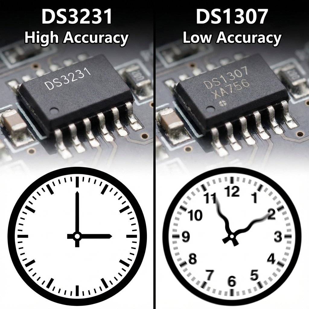
And worse, the Arduino’s internal clock is not accurate.
It drifts.
After a week, your Arduino clock might be off by 10 minutes.
If you are building a Pet Feeder or a Sprinkler System, this is unacceptable.
Today, we solve this with a dedicated Timekeeper. We are using the RTC (Real Time Clock) module. Specifically, the high-precision DS3231.

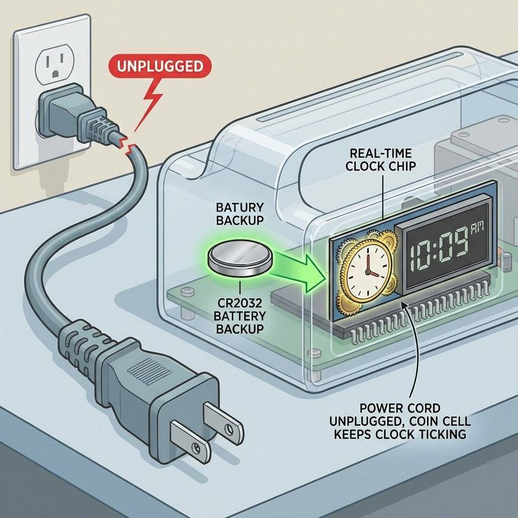
millis() isn’t enoughThe Arduino Uno has a “heartbeat” provided by a Resonator. It’s like a cheap wristwatch. It runs fast when it’s cold and slow when it’s hot. Also, when you unplug the power, the Arduino “forgets” the time. It resets to 0.
The Solution: The RTC Module An RTC is a separate chip that does one thing: Count Seconds.
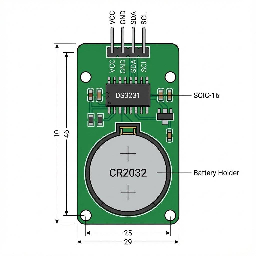
Independent Battery: It has a coin cell (CR2032) so it keeps ticking even when Arduino is off.
Precision Crystal: It uses a high-quality Quartz crystal.
Temperature Compensation (The Secret Sauce): Ordinary quartz crystals are sensitive to temperature. In cold weather, they vibrate faster. In hot weather, slower. This causes “drift”. A dollar-store digital watch might gain 2 minutes a month in winter.
The DS3231 Difference: Inside the black chip, there is a tiny thermometer sensor. Every 64 seconds, the chip measures the ambient temperature. It then physically adds or removes internal “load capacitors” to the crystal circuit to tune the frequency back to exactly . This is called a TCXO (Temperature Compensated Crystal Oscillator).
This is why we always recommend spending the extra $1 for the DS3231. For long-term data logging or sunrise/sunset timers, that drift matters.
To talk to this chip, we need a new language: I2C (Inter-Integrated Circuit).
Unlike digitalRead (1 wire per button) or Serial (Tx/Rx), I2C allows us to connect 127 devices using just Two Wires.
The Two Wires:
Every device on the bus has a unique Address.
$0x68$.$0x68$ on the SDA line, and only the RTC wakes up. The rest sleep.
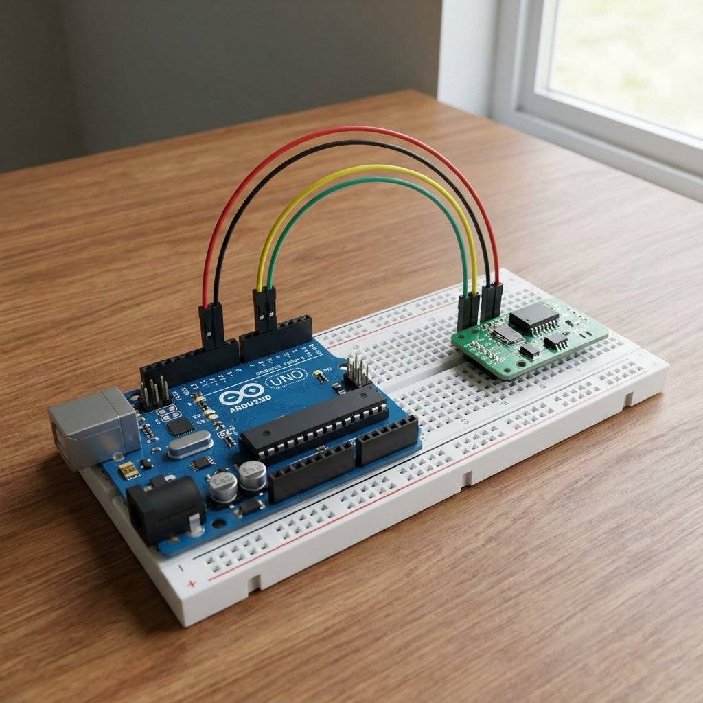
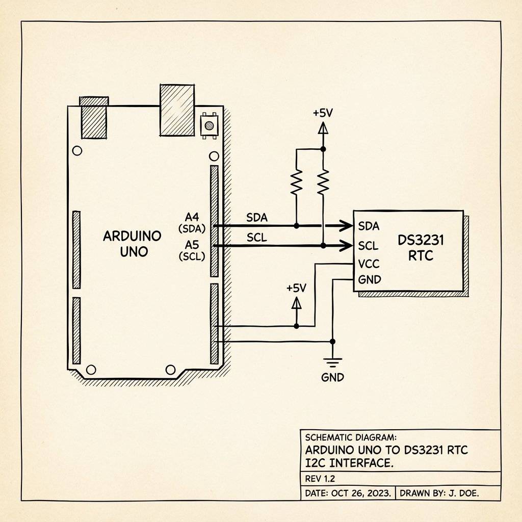
Start at the module on your desk. It has 6 pins (usually), but we only need 4.
VCC: Power ( to ). We use .
GND: Ground.
SDA: Connects to Arduino A4.
SCL: Connects to Arduino A5.
(SQW & 32K pins are for advanced interrupts. Ignore for now.)
The Battery: Make sure a CR2032 coin cell is inserted. This typically lasts 3-5 years.
It’s the simplest wiring since Day 1.
Note on Arduino Uno R3: There are dedicated SDA/SCL pins near the USB port. They are internally connected to A4/A5. You can use either.
Writing raw I2C bits is painful. We will use a library.
We recommend RTClib by Adafruit.
Open Arduino IDE.
Go to Tools -> Manage Libraries (or Ctrl+Shift+I).
Search for RTClib.
Install the one by Adafruit. (There are many RTC libraries, but Adafruit’s is the most beginner-friendly and widely supported).
Before we write code to talk to the RTC, let’s make sure the Arduino can “see” it. Sometimes wires are loose, or you swapped SDA/SCL. Run this simple “Scanner” sketch. It attempts to talk to every address from 0 to 127.
#include <Wire.h>

void setup() {
  Wire.begin();
  Serial.begin(9600);
  Serial.println("\nI2C Scanner");
}

void loop() {
  byte error, address;
  int nDevices = 0;

  Serial.println("Scanning...");

  for(address = 1; address < 127; address++ ) {
    Wire.beginTransmission(address);
    error = Wire.endTransmission();
    if (error == 0) {
      Serial.print("I2C device found at address 0x");
      if (address < 16) Serial.print("0");
      Serial.print(address, HEX);
      Serial.println("  !");
      nDevices++;
    }
  }
  if (nDevices == 0) Serial.println("No I2C devices found\n");
  else Serial.println("done\n");
  delay(5000);
}
What to look for:
If you see I2C device found at address $0x68$, Congratulations! Your RTC is alive.
If you also see $0x57$, that is the secret 32K EEPROM memory chip on the back of the module (we’ll talk about that later).
If you see No I2C devices found, check your wiring. SDA to A4, SCL to A5.
When you buy a new RTC, it doesn’t know the time. It thinks it is Year 2000. We need to set it once.
#include <Wire.h>
#include "RTClib.h"

RTC_DS3231 rtc;

void setup() {
  Serial.begin(9600);

  if (!rtc.begin()) {
    Serial.println("Couldn't find RTC");
    while (1); // Halt
  }

  // This line sets the RTC to the Date & Time this sketch was compiled
  rtc.adjust(DateTime(F(__DATE__), F(__TIME__)));
  // Or set explicitly: Year, Month, Day, Hour, Min, Sec
  // rtc.adjust(DateTime(2026, 1, 19, 12, 0, 0));
}

void loop() {
  // Nothing here. We just set the time once.
}
Upload this code.
The magic line rtc.adjust(DateTime(F(__DATE__), F(__TIME__))); grabs the time from your computer at the moment you hit Upload and sends it to the Arduino, which sends it to the RTC.
Now that the RTC is set, comment out the rtc.adjust() line and re-upload!
(If you don’t, it will reset the time to the compilation time every time you restart the Arduino).
Here is how to read the time:
#include <Wire.h>
#include "RTClib.h"

RTC_DS3231 rtc;
char daysOfTheWeek[7][12] = {"Sunday", "Monday", "Tuesday", "Wednesday", "Thursday", "Friday", "Saturday"};

void setup() {
  Serial.begin(9600);
  if (!rtc.begin()) {
    Serial.println("Couldn't find RTC");
    while (1);
  }
}

void loop() {
  DateTime now = rtc.now(); // Request data from I2C

  Serial.print(now.year(), DEC);
  Serial.print('/');
  Serial.print(now.month(), DEC);
  Serial.print('/');
  Serial.print(now.day(), DEC);
  Serial.print(" (");
  Serial.print(daysOfTheWeek[now.dayOfTheWeek()]);
  Serial.print(") ");
  Serial.print(now.hour(), DEC);
  Serial.print(':');
  Serial.print(now.minute(), DEC);
  Serial.print(':');
  Serial.print(now.second(), DEC);
  Serial.println();

  delay(1000);
}
Output:
2026/1/19 (Monday) 14:05:23
2026/1/19 (Monday) 14:05:24
It works! You are now reading time from a dedicated crystal chip.
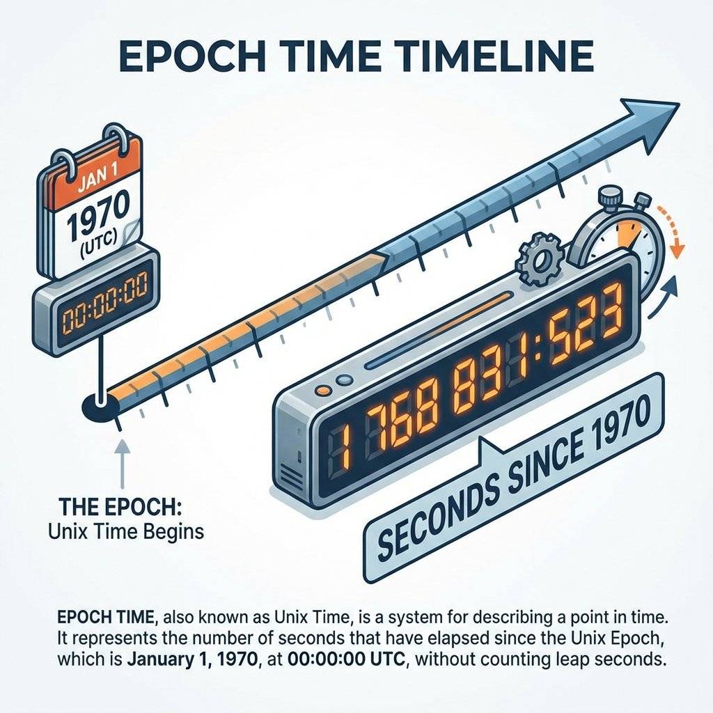
You might see a function called now.unixtime().
This returns a huge integer, something like 1768831523.
This is the Seconds since January 1, 1970.
Computers love this format.
TimeB - TimeA.The Y2038 Problem:
Old 32-bit systems will run out of seconds in the year 2038.
Luckily, the RTClib and Arduino moved to unsigned long or 64-bit recently, so we are safe until the sun explodes (mostly).
You might notice that I2C is “Open Drain”. This means devices can pull the line LOW (GND) to send a “0”. But they cannot push the line HIGH () to send a “1”. They just “let go” of the wire. To make the wire go back to , we need Pull-Up Resistors () connected between SDA/SCL and . Most DS3231 modules have these resistors built-in to the PCB. But if you build a raw circuit on a breadboard, don’t forget them, or I2C will fail!
We have been polling the time in the loop().
if (now.hour() == 8) ...
This wastes energy. The Arduino has to stay awake, burning power, just to check “Is it 8 yet?”
“Is it 8 yet?”
“Is it 8 yet?”
The DS3231 has a superpower: Hardware Alarms.
You can tell the RTC: “Wake me up at 08:00:00”.
Then you can put the Arduino to Deep Sleep (using a library like LowPower).
The Arduino shuts down completely (drawing nano-amps).
At 08:00:00, the DS3231 pulls its SQW (Square Wave / Interrupt) pin LOW.
If you connect SQW to Arduino Pin 2 (Interrupt 0), you can wake the Arduino up instantly.
This is how commercial devices run for years on a single battery. They don’t check the time. They wait for the time to check them. (We will cover detailed Sleep Modes in a future Advanced Project, but knowing this capability exists helps you design better systems today).
Look at the back of your DS3231 module.
Do you see a small 8-legged chip labeled 24C32?
That is a 32KB EEPROM (Electrically Erasable Programmable Read-Only Memory).
It shares the same I2C bus (Address $0x57$).
The RTC only stores the time.
But this chip can store Data.
If you are building a Data Logger (e.g., Temperature every hour):
Problem: “Couldn’t find RTC”
Problem: Time resets to restart time every boot
You forgot to comment out the rtc.adjust(...) line!
Every time the Arduino reboots, it runs setup(), which sets the time back to when you compiled the code.
Fix: Upload once with the line. Then comment it out // rtc.adjust(...) and Upload AGAIN.
Problem: Time resets to 2000/1/1 when power is cut
Problem: “165/165/85 (Unknown)”
2165/165/165, the I2C connection is unstable.You have a Servo Motor (Day 15/17 concepts) or a Relay (Day 18). You have an RTC (Day 19). Build a machine that dispenses food at 08:00 and 18:00.
if (now.hour() == 8 && now.minute() == 0 && now.second() == 0) {
   dispenseFood();
}
Issue: The loop runs thousands of times a second.
It might match 08:00:00 multiple times and dispense 50 times!
Fix: Use a bool fedToday flag.
if (now.hour() == 8 && !fedMorning) {
  dispenseFood();
  fedMorning = true;
}
if (now.hour() == 9) fedMorning = false; // Reset for tomorrow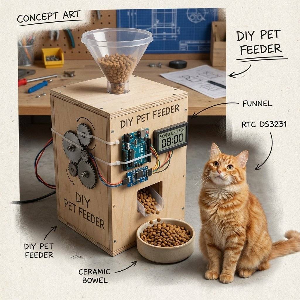
The LIR2032 vs CR2032 debate.
| Component | Quantity | Value | Notes |
|---|---|---|---|
| Arduino Uno | 1 | Any | The Master. |
| DS3231 Module | 1 | I2C | High precision RTC. |
| CR2032 Battery | 1 | Coin cell. | |
| Jumper Wires | 4 | M-F | Male-Female for the module. |
| Breadboard | 1 | Half | Optional. |
| OLED Display | 1 | 0.96” | Optional: For Days 20+. |
You have stepped out of the timeless void. Your Arduino now knows that it is a Monday. It knows when your birthday is (if you code it). Precision timing is the backbone of Logging data (Timestamping sensor readings) and Automation (Lights on at sunset).
We mentioned “LCDs and OLEDs” a few times. Currently, we are dumping data to the Serial Monitor. But you can’t carry a laptop with your digital watch. Tomorrow, on Day 20, we finally cut the cord. We will learn about Displays. Liquid Crystal (LCD) and the beautiful OLED. We will build a standalone clock that sits on your nightstand.
See you on Day 20.

KITT is calling. Learn how to build the legendary 'Knight Rider' scanning light effect using the CD4017 Decade Counter and a 555 Timer.
Read More →
1, 2, 4, 8... Learn the secret language of computers. We demystify Binary, explain the Ripple Counter, and build a 4-bit machine using the 74HC93 chip.
Read More →
Computers need amnesia? No. Learn how to trap an electron using Logic Gates. Master the SR Latch, D Flip-Flop, and build your own 1-Bit Memory cell.
Read More →