Time Travel: How to Build a Precision Digital Clock with Arduino & DS3231
Stop using delay() for time! Learn to master the DS3231 Real Time Clock (RTC), I2C protocol, and CR2032 battery backups to keep precise time for years.
Read More →
* SYSTEM.NOTICE: Affiliate links support continued laboratory research.
Yesterday (Day 8), we taught a rock to Remember. We built a single bit of memory. A cell that could hold a 0 or a 1. It was like teaching a child a single word. “Yes” or “No”.
Today, we teach the rock to Count. We are going to chain those memory cells together to create a machine that understands the passage of time. A machine that can count: 0, 1, 2, 3, 4…
This is the birth of Mathematics in silicon. This is how your watch knows seconds. This is how your car knows miles. This is how your computer knows memory addresses.
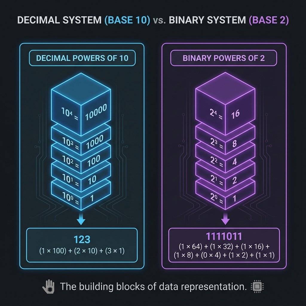
Before we touch a chip, we must understand the language of the machine. Humans count in Decimal (Base 10). Why? Because we have 10 fingers. 0, 1, 2, 3, 4, 5, 6, 7, 8, 9… What comes next? We run out of unique symbols. So we add a “1” to the left column and reset the right column to “0”. 10.
Computers don’t have fingers. They have switches (Transistors). A switch has only two states: OFF (0) or ON (1). So they count in Binary (Base 2).
In Decimal, every column is worth 10 times more than the last (1s, 10s, 100s, 1000s). In Binary, every column is worth 2 times more than the last.
Let’s look at 4 bits (a “Nibble”).
| Decimal | 8s Column | 4s Column | 2s Column | 1s Column | Binary |
|---|---|---|---|---|---|
| 0 | 0 | 0 | 0 | 0 | 0000 |
| 1 | 0 | 0 | 0 | 1 | 0001 |
| 2 | 0 | 0 | 1 | 0 | 0010 |
| 3 | 0 | 0 | 1 | 1 | 0011 |
| 4 | 0 | 1 | 0 | 0 | 0100 |
| … | … | … | … | … | … |
| 15 | 1 | 1 | 1 | 1 | 1111 |
Notice the pattern? The 1s column flips every time (0,1,0,1). The 2s column flips every two times (0,0,1,1). The 4s column flips every four times. The 8s column flips every eight times.
This is the key. To build a counter, we just need a circuit that flips half as fast as the one before it.
Humans count: 1, 2, 3.
Computers count: 0, 1, 2.
Why?
Because Zero is a value.
If you have 4 bits, you have 16 combinations ().
If you started at 1, you would count 1 to 16.
But “0000” (all switches off) is a valid state physically. If we ignored it, we would waste a state.
So we count 0 to 15.
This is called Zero-Indexing. It’s why array Item[0] exists in programming. It’s not to annoy you; it’s physics.
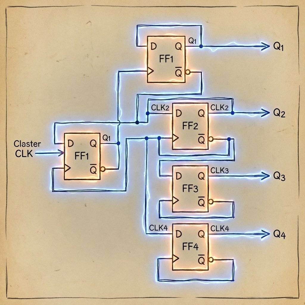
Recall the Flip-Flop from yesterday. It changes state (“toggles”) when the Clock signal hits it. What if… we take the Output (Q) of Flip-Flop A, and plug it into the Clock Input (CLK) of Flip-Flop B?
We have physically built the binary table above. This chain is called a Ripple Counter. Why “Ripple”? Because the change ripples through the chain like dominoes. A triggers B, B triggers C, C triggers D.
We could build this with two 74HC74 chips (since each has 2 flip-flops). But that’s messy wiring. Instead, we use a dedicated Counter chip: The 74HC93 (or 74LS93).
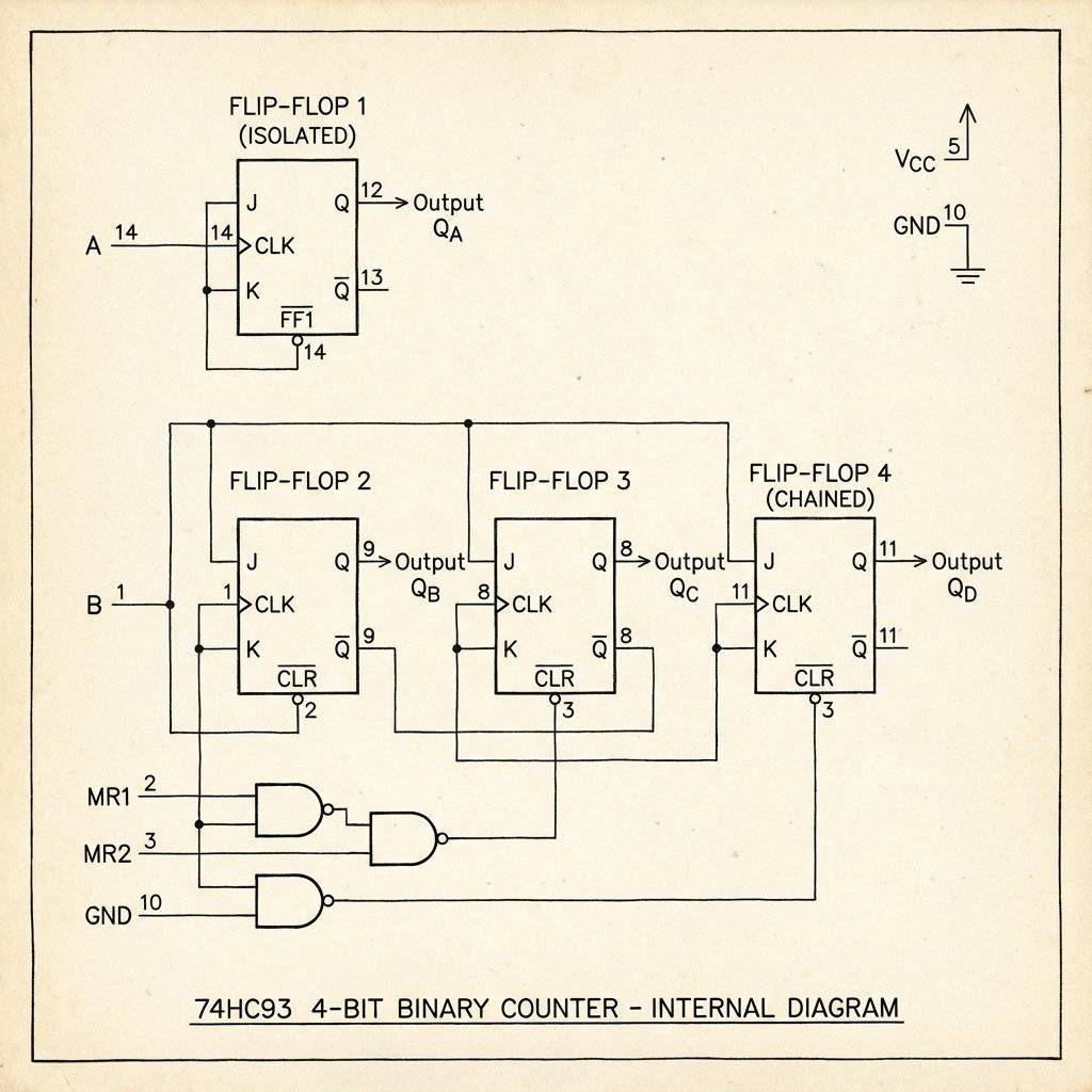
It contains four flip-flops pre-wired for us. Well, almost.
The 74HC93 is slightly weird. It is split into two parts:
Why is it split? Versatility. Sometimes you only need a divide-by-8 counter. To make a 4-bit (0-15) counter, we must manually connect the output of the first one to the input of the chain. WE MUST CONNECT Pin 12 (Q0) to Pin 1 (Input B). This bridges the gap and creates a single 4-bit chain.
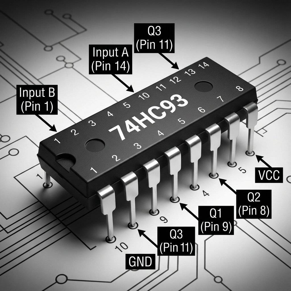
Pinout Breakdown:
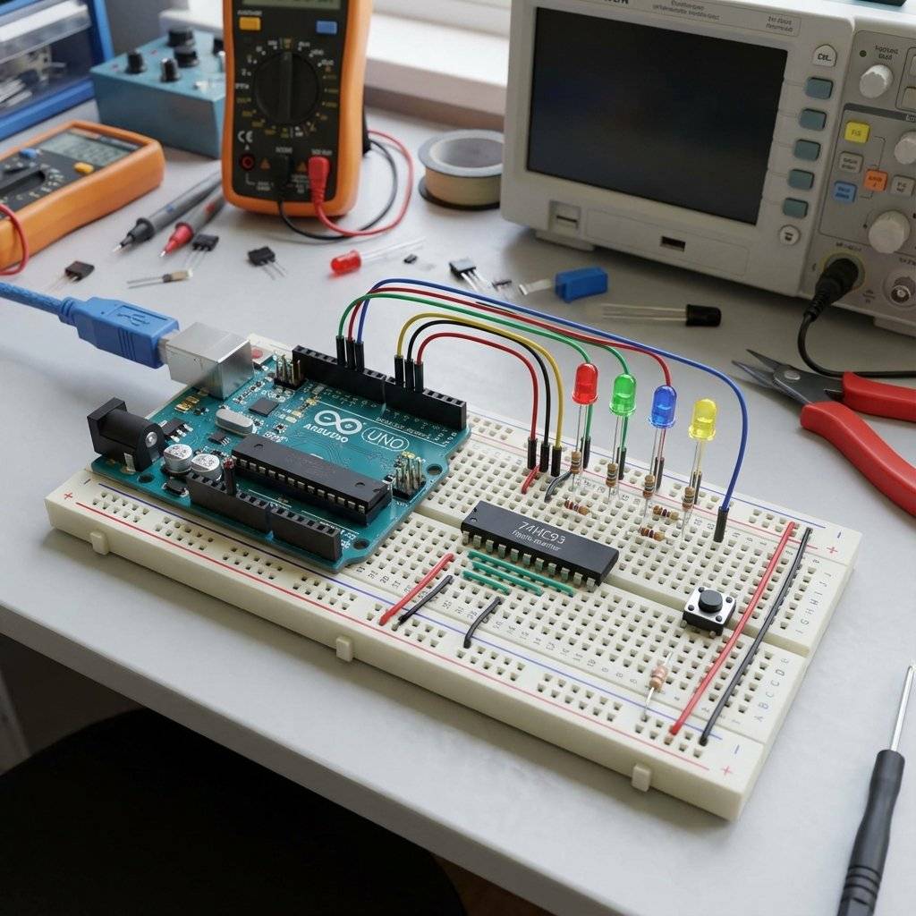
We are going to build a machine with 4 LEDs. We will press a button, and the LEDs will count up in binary.
0011…
Pay attention to the “External Bridge” wire.
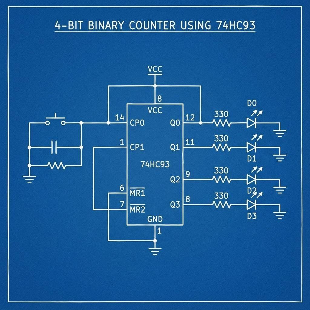
Critical Wiring Details:
Keeps going until 15 (1111), then resets to 0000.
Note: If it skips numbers, you have Switch Bounce! (See Day 8). Ideally, use a 555 Timer (Day 5) as the clock source for a smooth, automatic count.
Engineers visualize counters using Timing Diagrams. It looks like a staircase of waves.
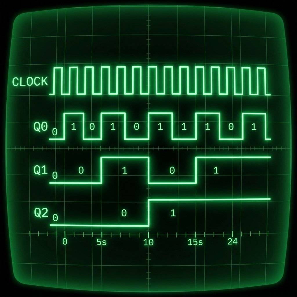
This is formally called Frequency Division. If you put a signal into Input A:
This is exactly how a digital watch works. It starts with a quartz crystal vibrating at . It divides by 2… fifteen times. The result is . One pulse per second. Your watch is just a 15-bit Ripple Counter.
Why don’t we use Ripple Counters in Supercomputers? Speed. Remember the dominoes? Domino A has to fall before it hits B. B has to fall before C. Each chip takes a tiny amount of time to react (nanoseconds). This is called Propagation Delay.
If you have a 64-bit counter: By the time the signal ripples from Bit 0 to Bit 63, the input clock might have already changed again! The number becomes corrupt for a split second. This “glitch” is unacceptable for high-speed processors. Solution: Humans invented Synchronous Counters (like the 74HC163). In these chips, all output bits change at the exact same instant. The Clock is wired to every flip-flop directly. It is harder to build, but much faster. For our LEDs? The Ripple Counter is fine. We can’t see nanoseconds.
The 74HC93 is infamous for destroying beginners’ confidence. Why? Because it breaks the rules.
If you feel confused, don’t worry. You are fighting 200,000 years of evolution. Our brains are wired for:
Analog magnitudes: “That lion is bigger than me.”
Base 10: “I have five fingers.” Thinking in Base 2 requires you to discard your intuition. In Binary:
1 + 1 = 10.
10 is not “Ten”, it is “One-Zero” (which is Two). It takes practice. But once you see the pattern, you see the matrix.
If you popped the lid off the 74HC93, you would see 4 Flip-Flops. Q0 is alone. Q1, Q2, Q3 are tied together. That’s why we need the external wire.
To build the 4-Bit Counter, you need:
| Component | Quantity | Value | Notes |
|---|---|---|---|
| 74HC93 | 1 | 4-Bit Binary Counter | Can also use 74LS93 |
| Push Button | 1 | Momentary Tactile | The Clock Source |
| LEDs | 4 | R, G, B, Y | To visualize the bits |
| Resistor | 4 | Current Limiting for LEDs | |
| Resistor | 1 | Pull-Down for Button | |
| Power | 1 | Source | USB/Battery |
| Breadboard | 1 | - | - |
| Jumper Wires | 10+ | Mixed Colors | - |
You might have seen computer codes like #FF00A2. That is Hexadecimal (Base 16).
Why do computer scientists use it?
Because Binary is annoying to read.
Imagine reading 1111000010100010. Your eyes would bleed.
Hexadecimal is a shortcut.
It groups 4 bits into one character.
So 1111 0000 becomes F 0.
It is just a way to zip up binary for humans. The computer still sees 1s and 0s.
The 74HC93 is just one member of a huge family.
You have built a 4-bit counter (Nibble). Can you build an 8-bit counter (Byte)? Goal: Connect two 74HC93 chips together. Hint: Take the Q3 (8s) output of the first chip and connect it to the Input A of the second chip. Now you have 8 LEDs. You can count from 0 to 255. If you pressed the button once per second, it would take you 4.25 minutes to fill the byte.
How does a computer count to a billion?
It chains 32 or 64 counters together.
But how does Counter A tell Counter B it is full?
It uses a Carry Flag.
When a counter rolls over from “1111” to “0000”, it sends a pulse.
This pulse is the “Carry”.
It goes into the Input of the next counter.
So: Max Value -> Carry -> Next Counter +1.
This simple mechanic allows us to chain infinite chips together to count the atoms in the universe.
Counters have limits. When they hit maximum (1111), they roll over to 0000.
This caused the Y2K Bug (2-digit decimal counters rolling from 99 to 00).
A similar bug is coming for Linux computers.
They count time as “Seconds since January 1, 1970” using a 32-bit signed binary counter.
On January 19, 2038, that counter will hit 0111...111.
The next second, it will flip to 1000...000.
In signed binary, the first bit is the +/- sign. 1 means negative.
So computer clocks will instantly flip to December 13, 1901.
Hopefully, by then, we will all be using 64-bit systems!
You have tamed the electron.
0001… 0010… 0011…
This 4-bit counter is the heart of every calculator, every calendar, every timer. But what if we could count… backwards? Or what if we could count to 9 and then stop (Decimal counting)?
Tomorrow, on Day 10, we will combine everything. We will take the 555 Timer (The Heartbeat) and connect it to a Decade Counter (The Brain) to build the classic “Knight Rider” scanner light. We are going to make the LEDs dance.
Safety Logic: Remember, Digital Logic is powerful. But it is also fragile. Static electricity from your finger can fry a CMOS chip like the 74HC93 in a microsecond. Always touch a grounded metal object (like your PC case) before picking up a chip. Respect the silicon.
See you tomorrow.

Stop using delay() for time! Learn to master the DS3231 Real Time Clock (RTC), I2C protocol, and CR2032 battery backups to keep precise time for years.
Read More →
KITT is calling. Learn how to build the legendary 'Knight Rider' scanning light effect using the CD4017 Decade Counter and a 555 Timer.
Read More →
Computers need amnesia? No. Learn how to trap an electron using Logic Gates. Master the SR Latch, D Flip-Flop, and build your own 1-Bit Memory cell.
Read More →