Time Travel: How to Build a Precision Digital Clock with Arduino & DS3231
Stop using delay() for time! Learn to master the DS3231 Real Time Clock (RTC), I2C protocol, and CR2032 battery backups to keep precise time for years.
Read More →
* SYSTEM.NOTICE: Affiliate links support continued laboratory research.
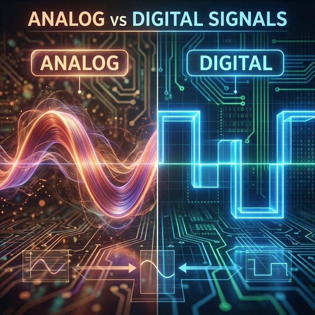
For the last six days, we have lived in the Analog world. In the analog world, things are “more or less.” A resistor limits “some” current. A capacitor stores “some” charge. A sensor reads “72% brightness.” It’s a world of infinite shades of gray.
Today, we cross the border into the Digital world.
The digital world is strict. It has no time for “maybe” or “sort of.” In this world, things are either TRUE or FALSE. ON or OFF. HIGH or LOW. 1 or 0.
This simple duality is the secret language of the universe’s most powerful machines. Your smartphone, your laptop, the internet itself—they are all just billions of tiny switches flipping between 1 and 0 faster than you can blink.
But how do you make a decision with just 1s and 0s? You need a structure. You need a way to combine these 1s and 0s to create meaning.
You need Logic Gates.
Before we dive into the specific gates, let’s appreciate why we use digital logic at all.
In the early days of electronics, everything was analog. If you wanted to send music over a radio, you sent a wave that looked exactly like the sound wave. If you wanted to store a picture, you stored it as analog film.
The problem with analog is Noise. If you send a signal of , and it picks up a little static (noise) along the wire, it might arrive as or . In analog, means something different than . The information has changed. The music gets crackly. The picture gets snowy.
Digital logic ignores small errors. In a digital system:
If you send a “1” signal at and it arrives at because of a terrible wire, the computer gate looks at it and says, “Eh, it’s above . That’s a 1.”
This “noise immunity” is why you can copy a digital file a billion times and the billionth copy is identical to the first. It is the bedrock of the Information Age.
A logic gate is a physical device that performs a “logical operation.” You give it one or more inputs, and it gives you a single output based on a specific rule.
If you think this sounds abstract, don’t worry. You already use logic gates every single day in your brain.
These three words—AND, OR, NOT—are the holy trinity of digital electronics. With just these three, you can build a processor that lands a rocket on Mars.
Let’s break them down, not with math, but with plumbing.
The AND gate is the strictest of them all. It looks at its inputs and says, “All of you must be TRUE, or the answer is NO.”
Imagine a water pipe with two valves installed in a row (in series).
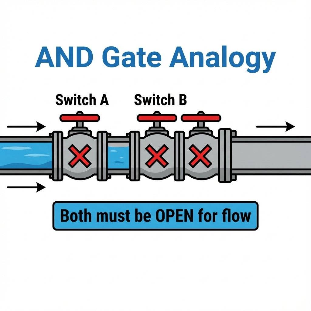
If you turn on Valve A but leave Valve B off, does water flow? No. The path is still blocked. If you turn on Valve B but leave Valve A off, does water flow? No. Only when Valve A AND Valve B are both open does the water flow through.
In electronics, we replace water with electricity, and valves with transistors inside a chip.
This lists all possible possibilities, which leads us to…
Engineers hate writing sentences like I just did above. Instead, we use a map called a Truth Table. It lists every possible input combination and what the output will be.
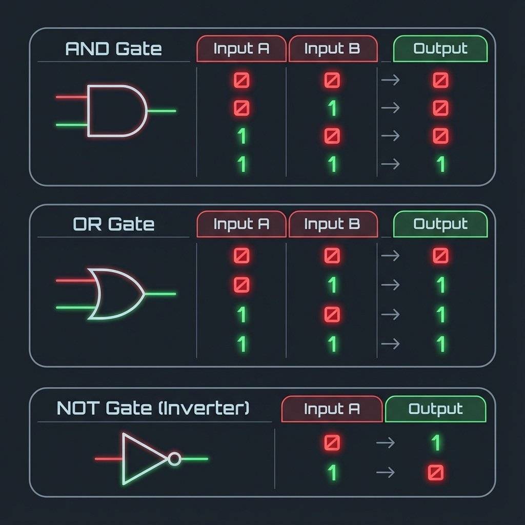
Look at the AND gate table (top). You see that lonely ‘1’ at the bottom? That’s the only way to get a YES from an AND gate. Perfection or nothing.
Where do we use AND gates?
The OR gate is much more relaxed. It says, “Hey, as long as one of you is TRUE, I’m happy.”
Imagine our plumbing again, but this time the pipe splits into two branches and then rejoins (parallel).
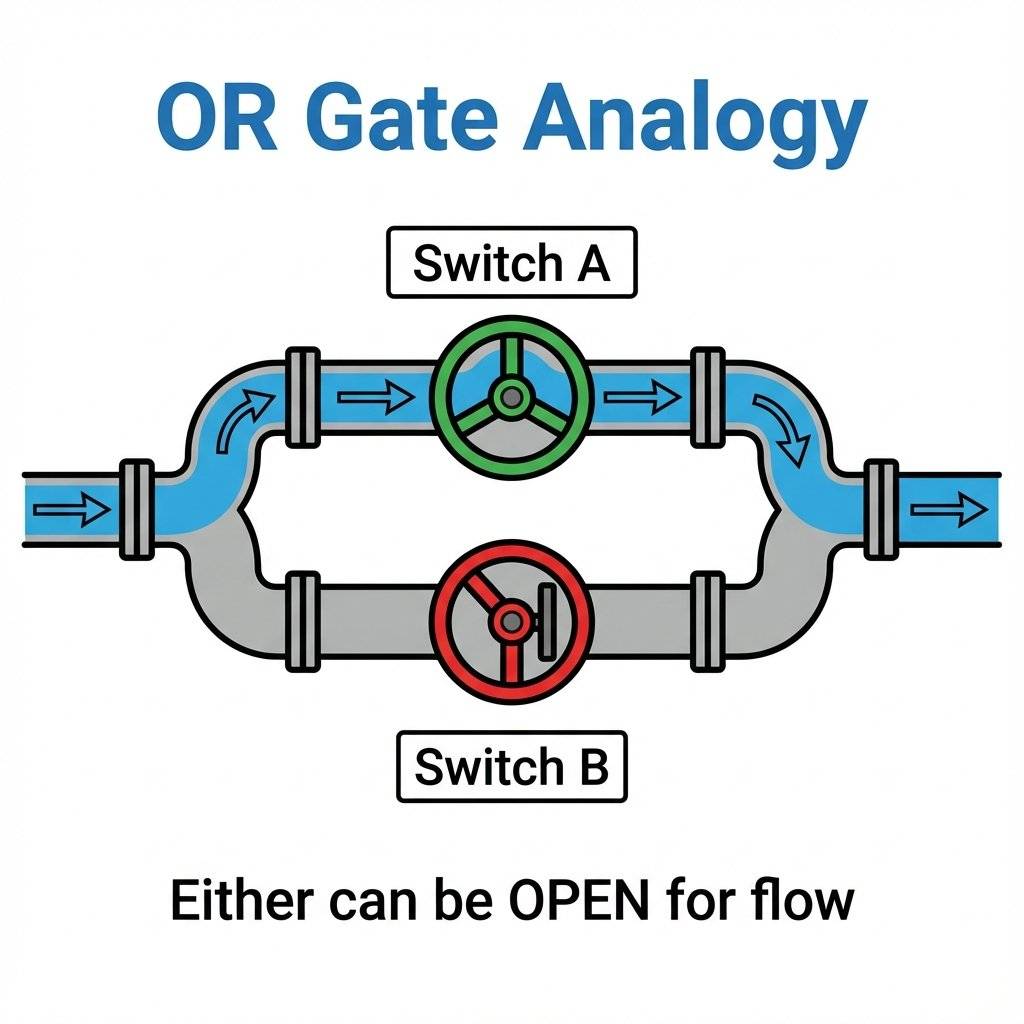
If you open Valve A, the water goes around Valve B and flows through. Flow (1). If you open Valve B, the water goes around Valve A and flows through. Flow (1). If you open BOTH, the water flows through both paths. Flow (1). The only time the water stops is if Valve A AND Valve B are both closed.
The OR gate is the optimist. It finds the ‘1’ in almost any situation. It represents possibility.
Where do we use OR gates?
The NOT gate is a bit weird. It is the only logic gate that has only one input. And whatever you tell it, it does the opposite.
It is also called an Inverter.
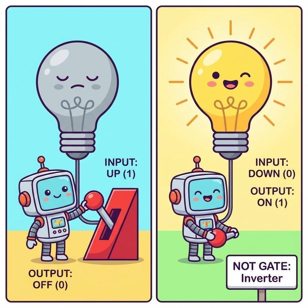
Why would you want a component that disagrees with you? It’s incredibly useful! Think of a nightlight. You want the light to turn ON only when the sun is NOT out. Sun = 1 (High Brightness) -> NOT Gate -> Light = 0 (Off). Sun = 0 (Darkness) -> NOT Gate -> Light = 1 (On).
Without the NOT gate, your automatic systems would only work when you didn’t need them, which would be hilariously useless. It is the key to automation. It turns a “positive” signals (sensor detecting something) into a “negative” action (stopping a motor), or vice-versa.
Once you master the big three, you meet the advanced cousins.
The OR gate we looked at earlier is actually an “Inclusive OR”. It says “A or B, or both, I’m cool with whatever.” The XOR gate is different. It stands for Exclusive OR. It says: “I want A or B, but NOT BOTH.” It is like ordering a combo meal where you can choose “Soup OR Salad.” You can have soup. You can have salad. But you cannot have both.
Why is XOR important? XOR is the secret to Math. Think about adding 1 + 1 in binary. The answer is 10 (which is 2 in decimal). The “0” part of that answer is calculated using an XOR gate. The “1” (carry) is calculated using an AND gate. Every time your computer adds numbers, plays a video game, or calculates a spreadsheet, billions of XOR gates are firing to do the math.
This is an AND gate followed by a NOT gate. It outputs 0 only if both inputs are 1. Otherwise it outputs 1. It sounds useless, but it is actually the “Universal Gate.” You can build ANY other gate (AND, OR, NOT, XOR) using only NAND gates connected in clever ways. This makes manufacturing chips cheaper because you only need to print one type of gate on the silicon wafer repeatedly. How to build everything with NAND:
Augustus De Morgan gave us a cheat code for simplifying logic.
When drawing circuit diagrams (schematics), we don’t draw little pictures of chips. We use special symbols.
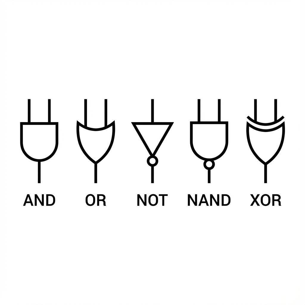
Memorize these shapes. They are the alphabet of electronics schematics. If you can read these, you can read the schematic for a supercomputer.
Okay, enough theory. How do we actually touch a logic gate? Do we buy a “Logic Gate”?
Yes and no. You buy a Chip (Integrated Circuit or IC).
The most famous family of logic chips is the 7400 Series. These black monolithic blocks have been around since the 1960s. They are the grandparents of modern computing. They powered the arcade machines of the 80s, the first home computers, and the control systems of the Apollo missions.
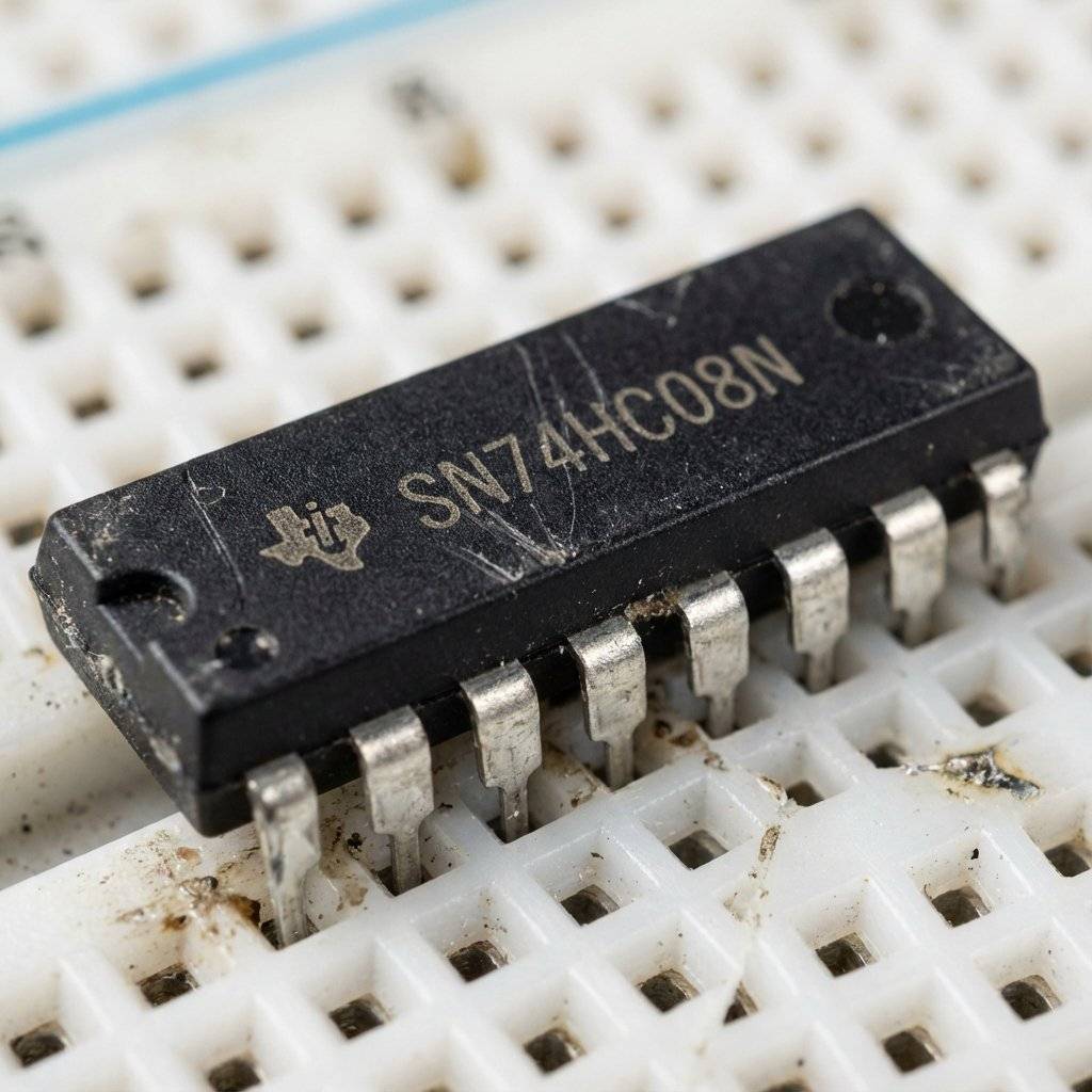
The chip in the image is a 7408. Inside that tiny black box are four separate AND gates.
Common 7400 Chips you should know:
To use them, you plug them into a breadboard. The legs are spaced exactly 0.1 inches apart, perfect for the holes.
Powering the Chip Every chip needs food. For the 7400 series, “food” is .
When buying chips, you see weird letters: SN74LS08, SN74HC08, SN74HCT08.
What do they mean?
WARNING: The Floating Input Problem This is where 99% of beginners fail. If you connect a push button to an input pin, when you press the button, the pin gets (Logic 1). Great. But what happens when you release the button? The pin is connected to… nothing. Just air. You might think that means 0V (Logic 0). WRONG.
Air is not “Zero Volts.” Air is an insulator, but it’s also full of noise. An unconnected input pin acts like an antenna. It picks up radio waves, static from your sweater, mains hum from the wall outlet ( or ). The input pin will “float” wildly, flipping between 0 and 1 randomly thousands of times a second. Your circuit will act possessed. LEDs will flicker, motors will twitch.
To fix this, we need to force the pin to be when the button is not pressed. We use a Pull-Down Resistor.
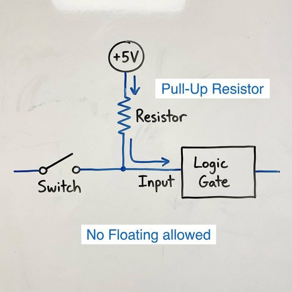
The resistor “pull pulls” the voltage explicitly to a known state () when the switch is open.
It’s like a spring on a door. When you push the door (Switch), it opens. When you let go, the spring (Resistor) pulls it back to closed. Without the spring, the door would just flap around in the wind (Float).
It’s time to build. We are going to construct a simple “Nuclear Launch Key” system. We want an LED (the missile launch) to fire ONLY if two separate officers (you and a friend, or two fingers) press their buttons at the exact same time.
If you press just Button A? Nothing. Just Button B? Nothing. Both together? ACTION.
This calls for the AND Gate.
Follow this diagram carefully. Notice the 7408 chip in the middle bridging the gap in the breadboard.
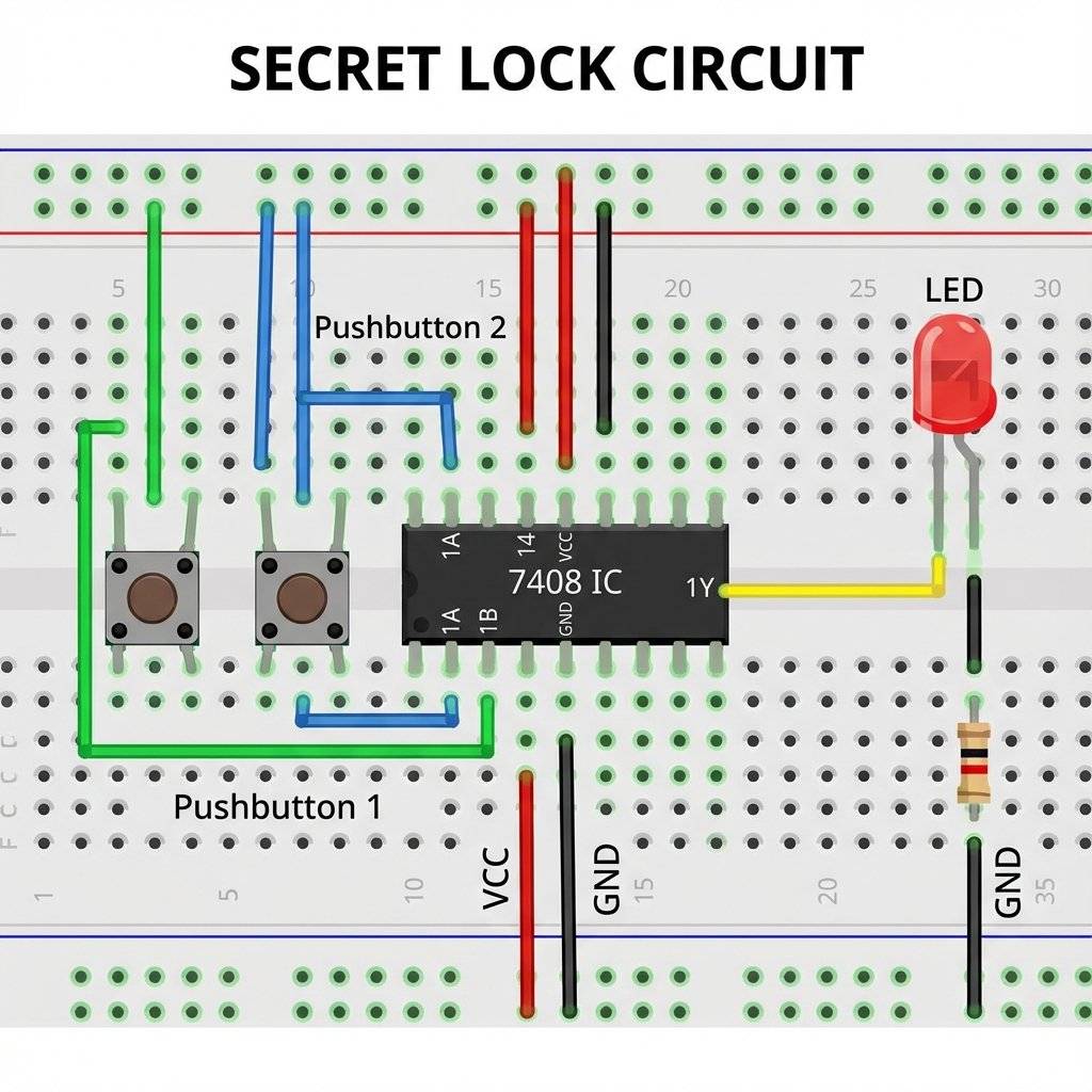
1. Insert the Chip Place the 7408 chip on the breadboard over the central ravine. Make sure the little notch or dot on the chip faces LEFT (or UP, depending on how you look at it). Pin 1 is to the left of the notch.
2. Power the Brain
Connect Pin 14 (Top Right) to the Red Rail (+).
Connect Pin 7 (Bottom Left) to the Blue Rail (-).
Check: Do this now. Don’t wait.
3. Install the Buttons Place two push buttons on the board. Make sure they straddle the ravine or are oriented correctly so the legs connect when pressed.
4. Wire the Inputs (The Logic)
Connect one side of Button A to the Red Rail (+).
Connect the other side of Button A to Pin 1 of the chip.
Connect one side of Button B to the Red Rail (+).
Connect the other side of Button B to Pin 2 of the chip.
Logic Check: When you press a button, goes into the pin.
5. Add the Pull-Downs (The Anchors)
Connect a resistor from Pin 1 to Ground (-) (Blue Rail).
Connect a resistor from Pin 2 to Ground (-) (Blue Rail).
Why? Remember the floating input! These resistors keep the inputs at “0” when buttons are released.
6. Wire the Output (The Result)
Connect your battery or USB power. The LED should be dark.
System Status: .
System Status: Input A=0, Input B=1. Result=0.
System Status: Input A=1, Input B=1. Result=1.
Troubleshooting if it doesn’t work:
(Bonus Section for the curious) You can write this entire circuit as a math equation. This math is called Boolean Algebra, named after George Boole who invented it in the 1800s (long before computers!).
AND is written as multiplication ( or just ). See? It’s just like regular multiplication!
OR is written as addition (). (In Boolean, there is no “2”. 1 is the maximum).
NOT is written as a bar over the letter (). If , then .
So, our secret lock circuit equation is simply: (Light = Button A AND Button B).
If we wanted the light to turn on if Button A is pressed OR if Button B is NOT pressed, the equation would be:
Engineers use this math to simplify huge complex circuits before they even build them. They solve the equation, simplify the terms, and end up using fewer chips.
Q: Can I use a battery? A: Be careful. Most 7400 series chips are designed strictly for . If you feed them , they might get hot and release the “magic smoke” (burn out). However, there is a CMOS version of these chips (74HC series) that can often handle to . Stick to USB power () or batteries () to be safe.
Q: Why is my chip getting hot? A: Unplug it immediately! You likely connected it backwards (VCC to GND or vice versa) or you have a “short circuit” on an output pin. Let it cool down, check your wiring, and try again.
Q: Pin 1 isn’t working, can I use other pins? A: Yes! Remember, a 7408 chip contains four separate AND gates. If Gate 1 (Pins 1, 2, 3) is broken, you can just move your wires to Gate 2 (Pins 4, 5, 6) or Gate 3 (Pins 9, 10, 8). It’s like having spare tires in the trunk.
Q: What is a “Breadboard”? A: If you skipped Day 3, go back and read it! A breadboard is that white plastic board we are plugging wires into. It lets us connect components without soldering.
The computer that flew the Apollo 11 astronauts to the moon in 1969 was called the Apollo Guidance Computer (AGC). It was the first computer in the world to use Integrated Circuits (ICs). But here is the crazy part: It was built almost entirely using NOR gates. Just one type of gate, repeated thousands of times. The engineers reasoned that if they used only one type of chip, they only had to test one type of chip. It made the computer incredibly reliable. It never crashed during a flight. Sometimes, keeping it simple is the smartest logic of all.
Today you took a massive step. You moved from simply letting electricity flow around a loop to controlling it based on rules. You built a machine that evaluates a condition and makes a decision.
That is the definition of computing.
The 7408 chip on your breadboard is a distant ancestor of the Core i9 or Apple Silicon chip in your computer. The modern chips just have billions of these gates packed into a space smaller than a fingernail, switching billions of times per second. But the rules—AND, OR, NOT—are exactly the same.
What’s Next?
Today you learned how computers make simple decisions. But a decision is fleeting. Once you let go of the button, the logic is gone. The LED turns off.
Computers need to Remember things. They need memory. They need to count.
Tomorrow, on Day 8, we will trap the electron.
We will learn about Flip-Flops and Latches, the circuits that allow computers to “remember” a bit of information even after you stop pushing the button.
We will build a circuit that toggles on and off with a single push—the basis of every “Power” button in existence.
We are moving from “Logic” to “Memory.”
Keep those chips powered up. I’ll see you tomorrow.

Stop using delay() for time! Learn to master the DS3231 Real Time Clock (RTC), I2C protocol, and CR2032 battery backups to keep precise time for years.
Read More →
KITT is calling. Learn how to build the legendary 'Knight Rider' scanning light effect using the CD4017 Decade Counter and a 555 Timer.
Read More →
1, 2, 4, 8... Learn the secret language of computers. We demystify Binary, explain the Ripple Counter, and build a 4-bit machine using the 74HC93 chip.
Read More →