Time Travel: How to Build a Precision Digital Clock with Arduino & DS3231
Stop using delay() for time! Learn to master the DS3231 Real Time Clock (RTC), I2C protocol, and CR2032 battery backups to keep precise time for years.
Read More →
* SYSTEM.NOTICE: Affiliate links support continued laboratory research.
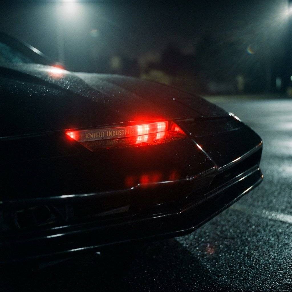
Today, we combine them all. We are going to build Art. We are going to build the most famous circuit in television history. The red, scanning eye of K.I.T.T. from Knight Rider. (Or the Cylon eye scan from Battlestar Galactica, if you prefer).
This project, known as an LED Chaser, is the “Hello World” of intermediate electronics. If you can build this, you are no longer a beginner.
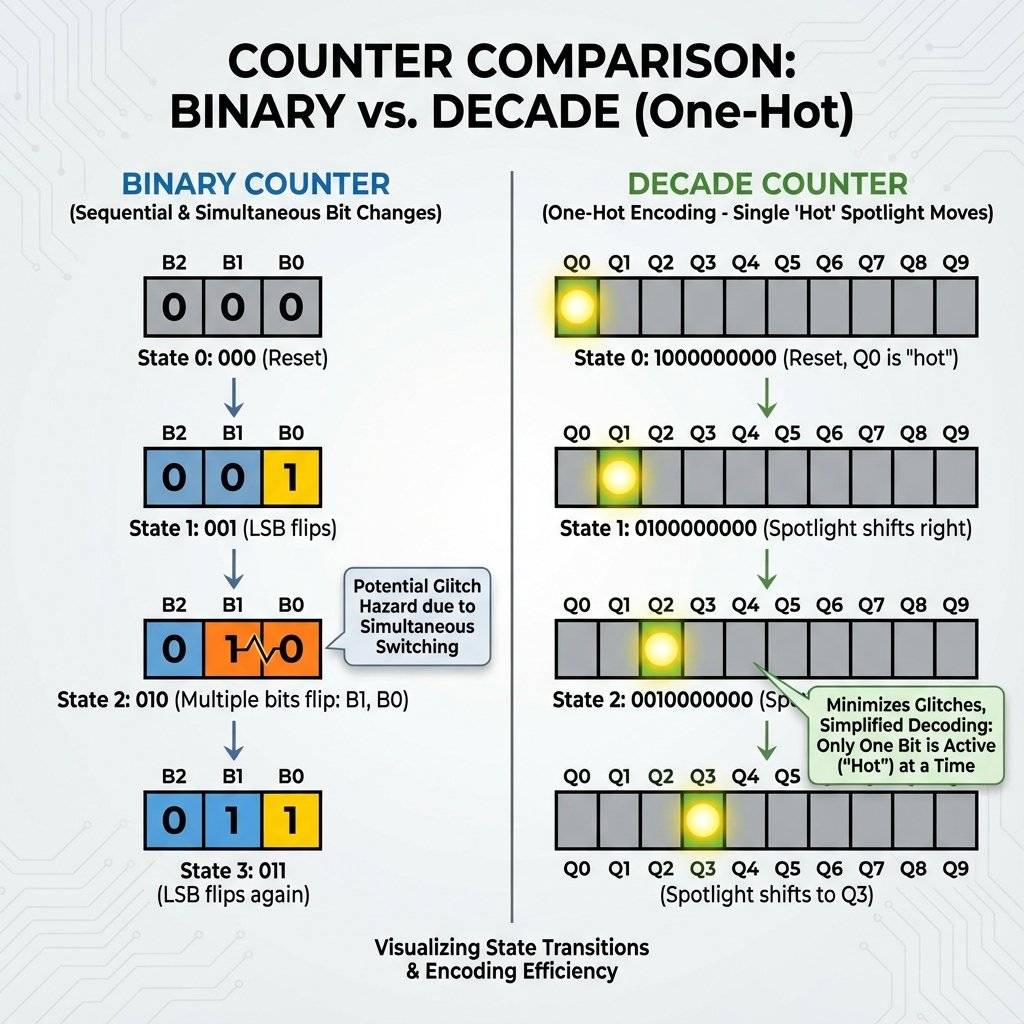
Yesterday, we used the 74HC93 Binary Counter. It counted in binary: 0000, 0001, 0010… That is great for computers, but terrible for humans. If you hook up LEDs to a binary counter, they look like a chaotic disco. They don’t “chase”.
To make LEDs turn on one at a time (1, then 2, then 3…), we need a different kind of counter. We need a Decade Counter. Enter the CD4017.
The CD4017 has 10 Output Pins (Q0 to Q9). Unlike the binary counter, the CD4017 uses “One-Hot” encoding. Only ONE output is High at a time. All others are Low.
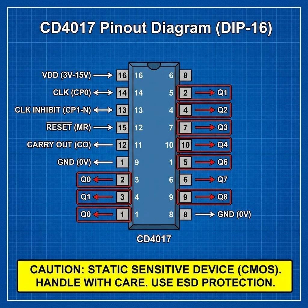
Technically, the CD4017 is a Johnson Counter (Twisted Ring Counter). Inside, it uses 5 D-Flip Flops in a chain. The output of the last Flip-Flop is inverted and fed back to the first. This creates a pattern of 00000 -> 10000 -> 11000… Then a complex logic decoder translates these weird states into the “One-Hot” outputs (Pin 3, Pin 2, etc.) that you see. This is why the pinout is so scrambled. The engineers prioritized the silicon layout over your convenience!
It is like a spotlight moving down a line of dancers.
Notice the name starts with CD (4000 series), not 74 (7400 series).
Because it is CMOS, it is extremely sensitive to static electricity. The 74HC93 from yesterday was tough. The CD4017 is fragile. Do not touch the pins after walking on carpet. Touch a metal table leg first!
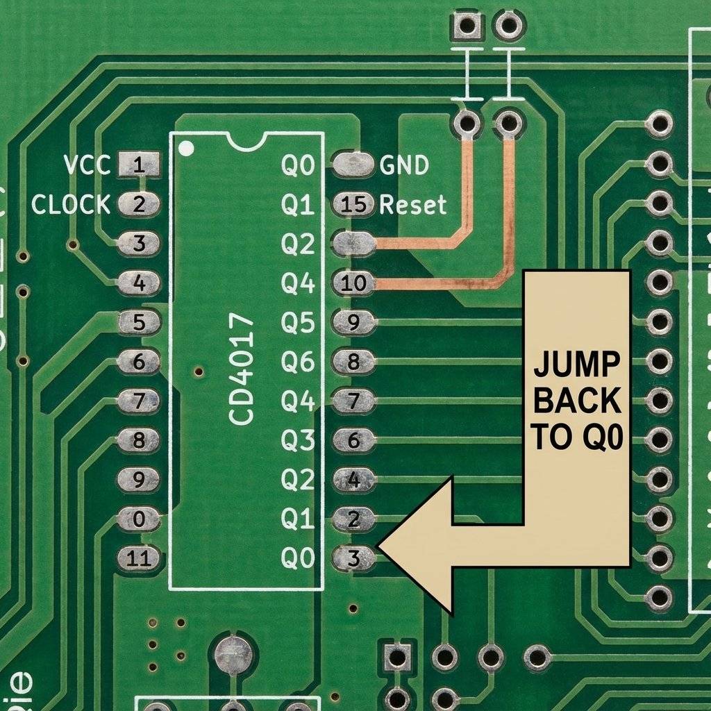
This chip is a DIP-16. It has 16 legs. The pin layout is… chaotic. The outputs are NOT in order. Q0 is Pin 3. Q1 is Pin 2. Q2 is Pin 4. Why? Because the silicon layout inside was easier that way. You Must follow the diagram. Do not guess.
Before we build K.I.T.T., let’s just make a simple 10-LED chaser. It will run from LED 1 to LED 10 and repeat.
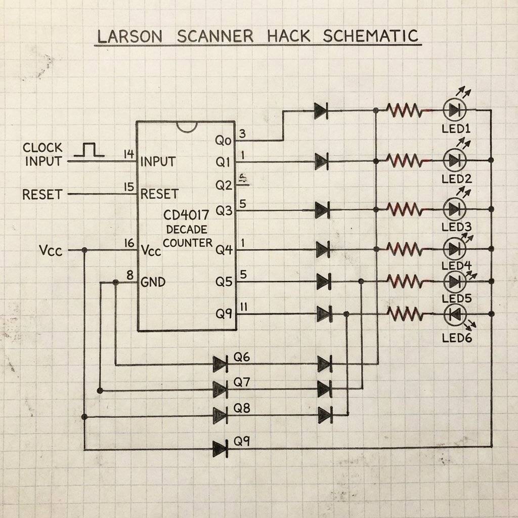
The CD4017 is just the legs. It needs a heart to beat. We will use our trusty 555 Timer (from Day 5) in Astable Mode to generate the pulses. The 555 output (Pin 3) connects to the CD4017 Input (Pin 14).
It looks like a spaghetti monster, but break it down. Left Side: Standard 555 Astable Circuit. Right Side: CD4017 with 10 LEDs.
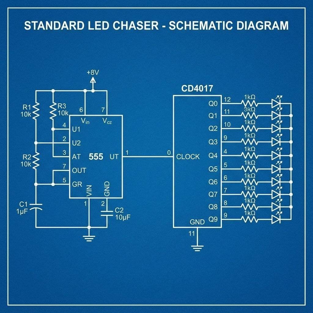
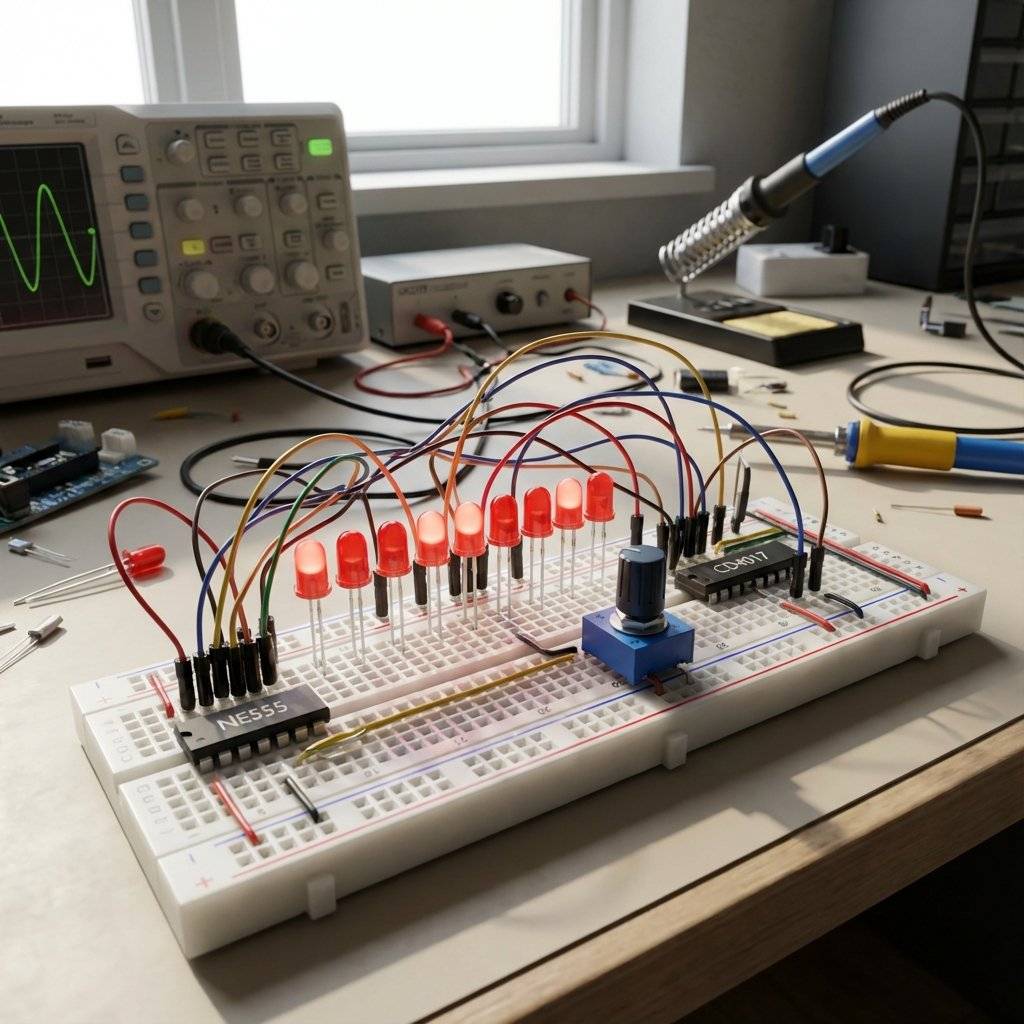
Turn it on. The LEDs should march one by one. Turn the potentiometer on the 555 to make them run faster or slower.
The simple chaser is cool, but it loops. 1-2-3-4-5-6-7-8-9-10 -> 1-2… K.I.T.T. didn’t loop. K.I.T.T. scanned Back and Forth. 1-2-3-4-5-6… 5-4-3-2-1.
How do we do that? Do we need a chip that counts backwards? (Those exist, like the CD4029, but they are expensive). We can cheat.
We don’t need the chip to count backwards. We just need to arrange the LEDs so it looks like it’s counting backwards. It’s a magic trick.
We use the 10 outputs to drive 6 LEDs. We double-wire the middle LEDs.
See? The counter is going forward (0 to 9), but the light bounces off the walls. We need Diodes (1N4148 or similar) on the double-wired connections to prevent the electricity from flowing backwards into the wrong pin.
Note: If you get “Ghosting” (weird LEDs lighting up), add 1N4148 diodes on the output pins. Or, for a simpler version without diodes: Just accept that two pins are fighting. While the CD4017 is often robust enough to survive, it is considered bad practice. Better method: Just stick to 10 LEDs in a circle to simulate a “Cylon Eye” loop if you don’t have diodes.

What if you only have 4 LEDs? You don’t want to wait for the counter to count to 10 (with 6 seconds of darkness) before it restarts. You want it to count 1-2-3-4 -> Reset.
The Solution: Connect the N+1 output to the Reset (Pin 15). If you want to count to 4 (Q0, Q1, Q2, Q3): Connect Q4 (Pin 10) to Reset (Pin 15). As soon as the chip tries to turn on Q4, it instantly touches the Reset button and jumps back to Q0. It happens so fast (nanoseconds) that Q4 never even lights up.
Why is it called that? It is named after Glen A. Larson, the television producer who created both Knight Rider (1982) and Battlestar Galactica (1978). He loved the scanning red eye effect.
Why is this circuit so satisfying? It represents persistence. It is a machine that is constantly searching. When you look at the waveform, it is a waterfall. When you look at the LEDs, it is a pendulum. It is the bridge between the digital world (discrete steps) and the physical world (motion).
What if you want to scan Light Bulbs? Or Horns? The CD4017 cannot do this. It will explode. You need Buffers. Connect each Output Pin to the Base of an NPN Transistor (2N2222). The Transistor then drives the heavy load (Relay or High-Power LED). This is how big Las Vegas signs work. A tiny brain chip controlling massive power transistors. Rule: Logic chips make decisions. Transistors move muscles.
| Component | Quantity | Value | Notes |
|---|---|---|---|
| CD4017 | 1 | Decade Counter | The Brain |
| NE555 | 1 | Timer | The Heart |
| LEDs | 10 | Red (Diffused) | Classic look |
| Resistor | 1 | For LEDs | |
| Resistor | 1 | For 555 | |
| Potentiometer | 1 | Speed Control | |
| Capacitor | 1 | 10uF | Timing |
| Diodes | 8 | 1N4148 | Optional (for Scanner) |
What if 10 LEDs aren’t enough? What if you want to count to 100? You can Cascade these chips, just like we did with the Binary Counters. But it’s tricky. Ideally, when Chip A finishes (Pulse 10), it should trigger Chip B to move one step. The Secret Pin: Pin 12 (Carry Out).
We mentioned static electricity, but there is another killer. Floating Inputs. In TTL chips (74xx), an unconnected input usually defaults to High. In CMOS chips (40xx), an unconnected input is… undefined. It becomes a radio antenna. It picks up hum from your wall wiring. If you leave an input pin floating, your chip might oscillate at times a second, get super hot, and die. Rule: ALWAYS connect unused inputs to VCC or GND. Never leave them floating.
This chip isn’t just a toy.
You have finished the “Hardware” phase. Can you answer these before moving to “Software” tomorrow?
If you hesitated, look back. Tomorrow, we write code.
You made it. Ten days ago, you didn’t know what a voltage divider was. Today, you built a self-clocking, sequential logic scanning array. That is massive progress.
You have now completed Part 1: The Fundamentals.
Tomorrow, we change the game. We stop wiring logical chips manually. We start Coding. We are going to introduce the Arduino Uno. We will replace that mess of wires on your breadboard with a few lines of C++ code. Get your USB cables ready. The software era begins.
See you on Day 11.
Let’s pause and look at your breadboard. Ten days ago, it was empty. Now, you likely have a collection of resistors, capacitors, chips, and wires that looks like a rat’s nest. This is good. This is learning. Here is what you have mastered:
You effectively built a 1970s computer from scratch.
For the next 10 days, we are going to change the rules. We are moving to the Arduino. To prepare, you might need to order some new parts if you don’t have them:
Why change? Building that Knight Rider circuit took 2 chips, a capacitor, a pot, and 20 wires. With an Arduino, it takes Zero chips and 10 wires. We replace the hardware complexity with software complexity. It is cleaner. It is faster. But it is different. You need to learn to type code.
Before you tear down your 4017 circuit… Try to make it “Bounce” without the extra LEDs. Can you use the outputs to trigger a second 555 timer that changes the speed? Can you make it speed up and slow down like a heartbeat? The chip has no brain, but you do. Be creative.
End of Part 1.

Stop using delay() for time! Learn to master the DS3231 Real Time Clock (RTC), I2C protocol, and CR2032 battery backups to keep precise time for years.
Read More →
1, 2, 4, 8... Learn the secret language of computers. We demystify Binary, explain the Ripple Counter, and build a 4-bit machine using the 74HC93 chip.
Read More →
Computers need amnesia? No. Learn how to trap an electron using Logic Gates. Master the SR Latch, D Flip-Flop, and build your own 1-Bit Memory cell.
Read More →