From Code to Reality: Building a Production-Grade IoT Device
A complete, end-to-end guide on building a secure, scalable IoT device using ESP32, MQTT, and AWS IoT Core. We bridge the gap between software logic and hardware reality.
Read More →
* SYSTEM.NOTICE: Affiliate links support continued laboratory research.
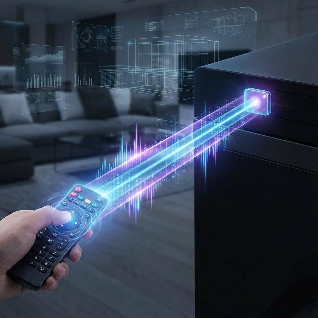
We are entering the world of Wireless Communication. And we are starting with the technology that has been sitting on your coffee table for 40 years: Infrared (IR). By the end of this guide, you won’t just turn on an LED. You will decode the secret language of your Samsung TV remote. You will build a “Smart Plug” that turns on your desk lamp when you press “Volume Up”. You will become the master of the invisible waves.
Light is a wave. Our eyes can see wavelengths from 400nm (Violet) to 700nm (Red). If you make the wavelength just a little bit longer (700nm - 1mm), it becomes invisible to us. This is Infrared.
It behaves exactly like visible light. It bounces off mirrors. It is blocked by walls. But to a silicon sensor (photodiode), it shines as bright as a flashlight.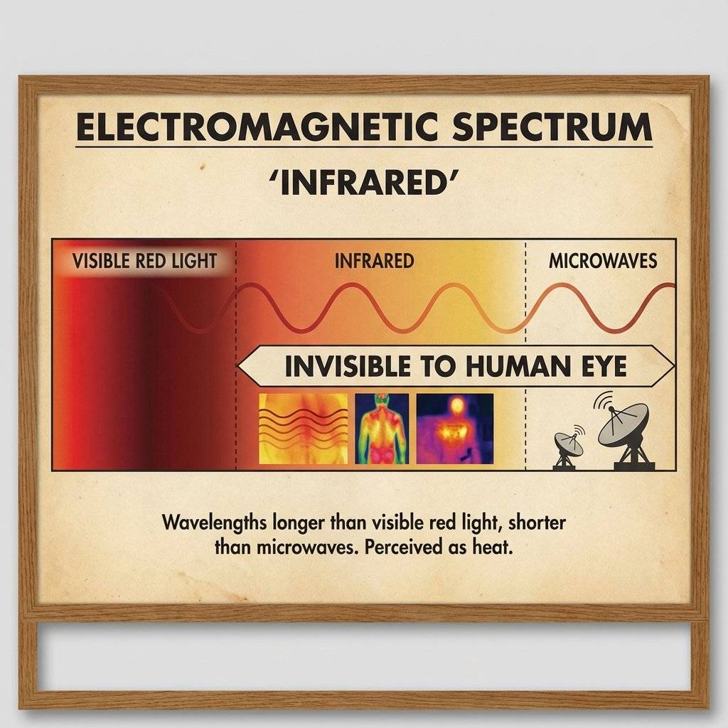
The sun pumps out massive amounts of IR radiation. Light bulbs emit IR. Your toaster emits IR. If we just flashed an IR LED to send data, the receiver would be blinded by the “ambient noise” of the universe. It would be like trying to whisper in a rock concert.
To fix this, engineers don’t just turn the LED ON. They blink it ON and OFF really fast—specifically 38,000 times per second (38kHz). The Receiver (VS1838B) is tuned to only see 38kHz.
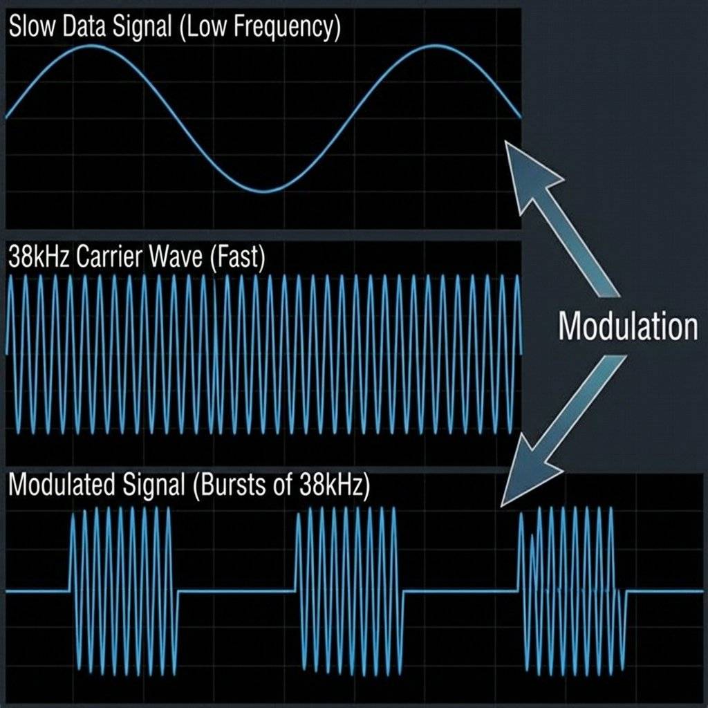
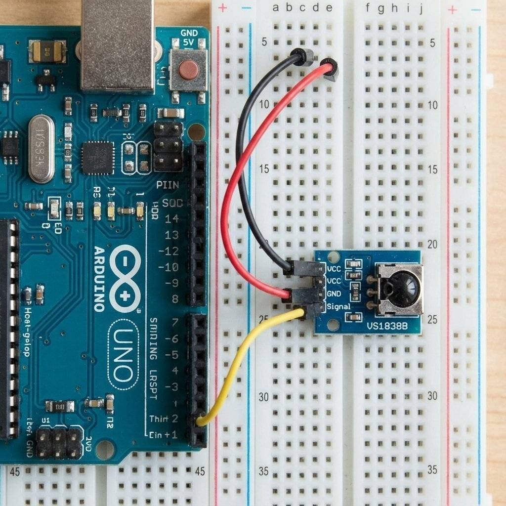
You don’t need a PhD to use this. You need a VS1838B. It is a 3-pin black component with a metal cage. Inside, it has filters, amplifiers, and a demodulator. It outputs a clean digital signal (LOW/HIGH) that the Arduino can read easily.
Pinout:
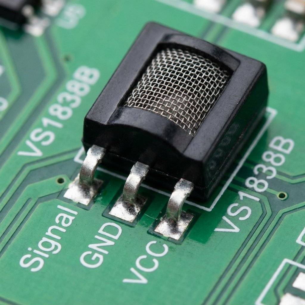
Why can you use your remote even with the lights on? The VS1838B isn’t just a “Light Sensor”. If it were, it would be useless during the day. Inside that black epoxy case is a high-tech Bandpass Filter.
Simple.
Most remotes use the NEC Protocol. It is a timing-based language.
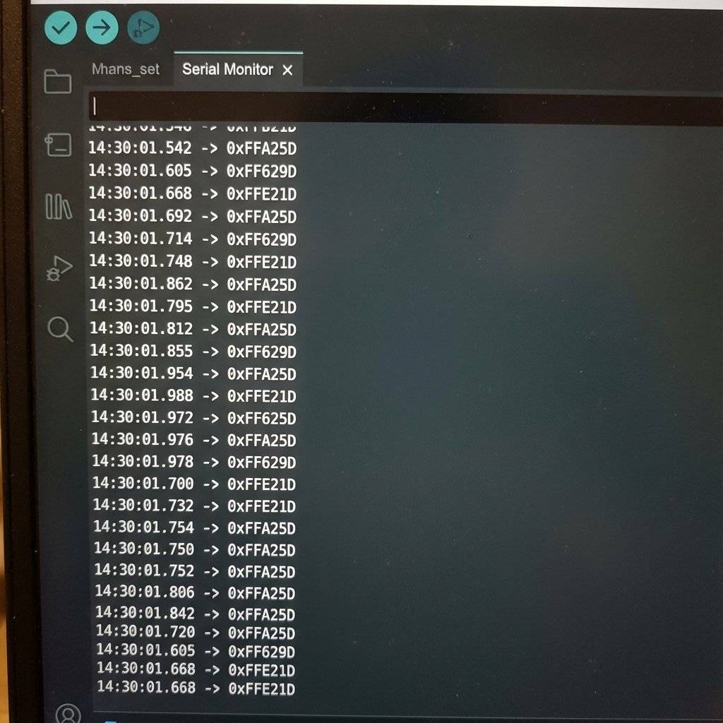
You will see codes like $0xFFA25D$.
Why not just use “16753245”?
Binary is too long: 1111 1111 1010 0010 0101 1101
Decimal is random: 16,753,245
Hexadecimal splits the binary into groups of 4.
1111 = F1010 = A
It maps perfectly to the bits. Low-level engineers love Hex because it reveals the structure of the data. Use it. Love it.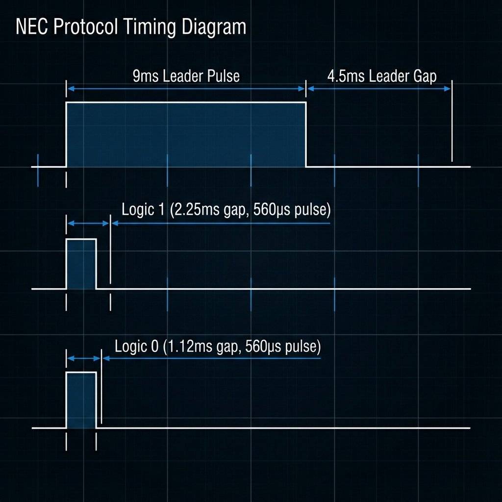
How does the receiver know the difference between a 0 and a 1?
It is all about the Gap.
The Arduino measures these gaps with microsecond precision.
If the gap is short, it writes a 0 to the variable.
If the gap is long, it writes a 1.
This happens 32 times per message (8 bits Address + 8 bits ~Address + 8 bits Command + 8 bits ~Command).
We will use the IRremote library.
Note: In 2024/2025, this library hit version 4.0+. The syntax changed drastically from the old tutorials you might find online. We will use the MODERN syntax.
Step 1: Install IRremote by Armin Joachimsmeyer via Library Manager.
The Code (The Sniffer): This code will print the Hexadecimal code of any button you press.
#include <IRremote.hpp> // Use the .hpp for v4.0+

const int IR_PIN = 2; // Receiver connected to Pin 2

void setup() {
  Serial.begin(9600);
  while (!Serial); // Wait for Serial to become ready
  Serial.println("IR Receiver Ready. Aim remote and fire!");

  // Start the receiver
  IrReceiver.begin(IR_PIN, ENABLE_LED_FEEDBACK);
}

void loop() {
  if (IrReceiver.decode()) {
    // We found a signal!
    // Print the raw protocol data (useful for debugging)
    Serial.println("----------------------------------------");
    Serial.print("Protocol: ");
    Serial.print(IrReceiver.getProtocolString());
    Serial.print(" | Command: 0x");
    Serial.println(IrReceiver.decodedIRData.command, HEX);
    // Check for "Repeat" flag (User holding button down)
    if (IrReceiver.decodedIRData.flags & IRDATA_FLAGS_IS_REPEAT) {
      Serial.println(" (Repeat)");
    }
    // Print Raw Timing Data (For unknown protocols)
    // IrReceiver.printIRResultRaw(&Serial);
    // Prepare for next signal
    IrReceiver.resume();
  }
}When you press a button, you are looking for the Command. Ignore the Address for now (unless you have two of the same TV).
0x5D (Example)0x1D (Example)0x12 (Example)The “Unknown” Protocol
Sometimes you will see Protocol: UNKNOWN.
This means your remote uses a weird standard (maybe an air conditioner?).
In this case, you cannot use the Hex code easily.
You must record the Raw Timings (the exact microseconds of every pulse) and play them back exactly.
This is how “Universal Learning Remotes” work.
Now that we know “Volume Up” is $0x5D$, we can make the Arduino react.
Let’s hook up a Relay (Day 18) to Pin 7.
#include <IRremote.hpp>

const int IR_PIN = 2;
const int RELAY_PIN = 7;

// CHANGE THESE to matches your specific remote!
const int CODE_VOL_UP = 0x5D; // Example
const int CODE_VOL_DOWN = 0x1D; // Example

void setup() {
  Serial.begin(9600);
  IrReceiver.begin(IR_PIN);
  pinMode(RELAY_PIN, OUTPUT);
  Serial.println("Smart Plug Ready.");
}

void loop() {
  if (IrReceiver.decode()) {
    int command = IrReceiver.decodedIRData.command;
    Serial.print("Received: 0x");
    Serial.println(command, HEX);
    // The Magic Switching Logic
    if (command == CODE_VOL_UP) {
      Serial.println("Turning Lamp ON");
      digitalWrite(RELAY_PIN, HIGH);
    }
    else if (command == CODE_VOL_DOWN) {
      Serial.println("Turning Lamp OFF");
      digitalWrite(RELAY_PIN, LOW);
    }
    IrReceiver.resume(); // Essential! Don't forget this.
  }
}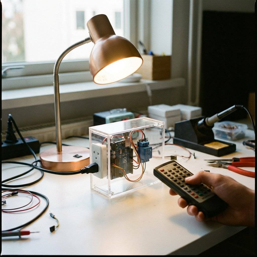
Receiving is fun. Sending is power.
You can program your Arduino to turn off every TV in a bar (The TV-B-Gone concept). To send IR, you simply connect an IR LED to Pin 3 (PWM). **Crucial:** You cannot drive an IR LED directly from a pin for long ranges. You need a transistor (2N2222) to pump 100mA through it for a strong signal. ```cpp #includeconst int SEND_PIN = 3; // Fixed for Uno in library
void setup() { Serial.begin(9600); IrSender.begin(SEND_PIN); // Initialize sender }
void loop() { Serial.println(“Sending MUTE command…”); // Send NEC code (Address 0x00, Command 0x5D, Repeats 0) // You need to know the full Address/Command from Part 1 IrSender.sendNEC(0x00, 0x5D, 0); delay(5000); // Annoy people every 5 seconds }

### The “Send Raw” Technique (For Air Conditioners)
TVs use short codes (32 bits).
Air Conditioners send **massive** packets (100+ bits).
- Use `IrSender.sendRaw()` for complex devices.
- Capture the raw timing array using `printIRResultRaw`.
- Copy that huge array into your code.
- Blast it out.
## Troubleshooting
**1. Code is 0x0 or Random?**
If you hold the button down, many remotes send a “Repeat Code” (Flag).
In the NEC protocol, this is a special short signal that says “Use the previous command again”.
If you are writing code to change volume, you **WANT** to detect this.
- **Without Repeat Logic:** You have to press Vol+ 50 times.
- **With Repeat Logic:** You hold Vol+ and it zooms up.
`if (IrReceiver.decodedIRData.flags & IRDATA_FLAGS_IS_REPEAT)` is your friend.
**2. Sunlight Issues**
If your project works indoors but fails outdoors, that’s the sun.
Sunlight saturates the sensor.
**Fix:** Put the sensor in a black tube (like a straw) to block side-light.

## Challenge: The Secret Knock
Remotes are boring.
Build a “Secret Knock” receiver.
Instead of checking for a specific button, checking for a specific **Timing Sequence**.
Or, create a “Laser Tripwire” using a continuous 38kHz beam. If the beam breaks, the alarm sounds.
## Challenge 2: DIY Laser Tag
You have a transmitter (IR LED). You have a receiver.
You have the building blocks of **Laser Tag**.
- **The Gun:** IR LED + Button.
- **The Vest:** IR Receiver + Buzzer.
- **The Logic:** `if (command == HIT) { lives--; }`
Use a lens to focus the IR LED beam for range.
Suddenly, you aren’t just blinking LEDs. You are building a game for your friends.
## The Bill of Materials (BOM)
| Component | Quantity | Value | Notes |
| :--- | :--- | :--- | :--- |
| **Arduino Uno** | 1 | Any | The Brain. |
| **VS1838B** | 1 | 38kHz | IR Receiver module. |
| **IR LED** | 1 | 940nm | For transmitting signals. |
| **Resistor** | 1 | $220\Omega$ | For the LED. |
| **Transistor** | 1 | 2N2222 | Recommended for TX range. |
| **TV Remote** | 1 | Any | For decoding/testing. |
## The Engineer’s Glossary (Day 27)
- **IR (Infrared):** Light waves >700nm.
- **Modulation:** Blinking a signal to separate it from noise.
- **Carrier Frequency:** The speed of the modulation (38kHz).
- **NEC Protocol:** Timing-based language for IR remotes.
- **Photodiode:** Semiconductor that converts light to electricity.
## Conclusion
You have mastered the invisible spectrum.
You can now control 110V appliances from your couch.
You can clone your lost remote.
You can build robots that talk to each other using flashes of light.
**Next Up:**
We stay wireless.
But IR requires “Line of Sight”. You have to point at it.
Tomorrow, we break down walls.
We are moving to **Radio Frequency (RF 433MHz)**.
We will send data through walls, across the house, and build a long-range weather station.
See you on Day 28.
A complete, end-to-end guide on building a secure, scalable IoT device using ESP32, MQTT, and AWS IoT Core. We bridge the gap between software logic and hardware reality.
Read More →
WiFi barely reaches your driveway. LoRa reaches the next town. Master the SX1278 module, Chirp Spread Spectrum physics, and build a 5km range sensor network.
Read More →
Stop polling your server every 5 seconds. Learn why Professional IoT uses MQTT. Master Pub/Sub architecture, QoS levels, Retained Messages, and Last Will & Testament.
Read More →