LoRa: How to Send Data 5km with Arduino (No WiFi)
WiFi barely reaches your driveway. LoRa reaches the next town. Master the SX1278 module, Chirp Spread Spectrum physics, and build a 5km range sensor network.
Read More →
* SYSTEM.NOTICE: Affiliate links support continued laboratory research.
Welcome to Day 10 of “The Software Developer’s Hardware Journey.”
If you’ve been following along, we’ve come a long way. We started with the humble LED, moved through the mysteries of Ohm’s Law, wrestled with datasheets, and finally designed our own PCB. Today, we cross the final frontier: The Internet of Things (IoT).
For a software developer, IoT is the sweet spot. It’s where the physical world we’ve been learning to control finally meets the data-driven world we know and love. But let me be clear: “Hello World” in IoT isn’t just blinking an LED anymore. It’s blinking an LED from a continent away, securely, reliably, and with telemetry.
Today, we are going to build a production-grade environment monitor. This isn’t a toy. It’s a vertical slice of a real-world product, involving:
Let’s build something real.
As web developers, our instinct is to send a POST request.
In the world of constrained devices, HTTP is heavy. It requires opening a connection, sending headers, waiting for a response, and closing the connection. It’s chatty and power-hungry.
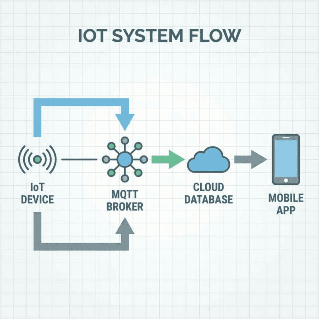
Instead, we use MQTT (Message Queuing Telemetry Transport).
MQTT is a lightweight, publish-subscribe protocol running over TCP/IP. It’s designed for erratic networks and low power.
device/123/temp).This decoupling is powerful. Our device doesn’t know or care who is listening. It just reports its state and goes back to sleep.

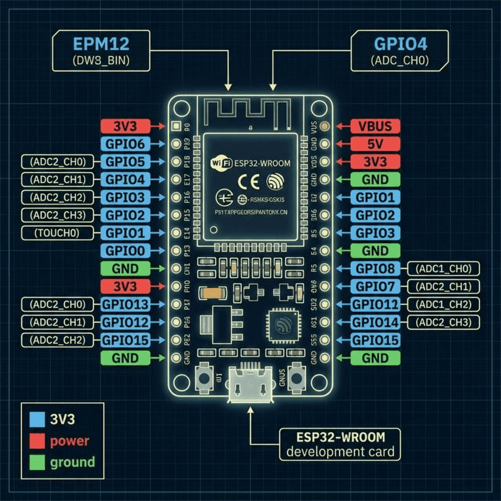
We are using the ESP32 for this project. Unlike the Arduino Uno regarding which we spoke in Post 7, the ESP32 is a beast. It has dual cores, built-in WiFi and Bluetooth, and enough RAM to handle TLS encryption—a non-negotiable requirement for modern IoT.
Here is the pinout we need to be aware of. Notice the multiple power rails and the dedicated layout for ADC and communication protocols.
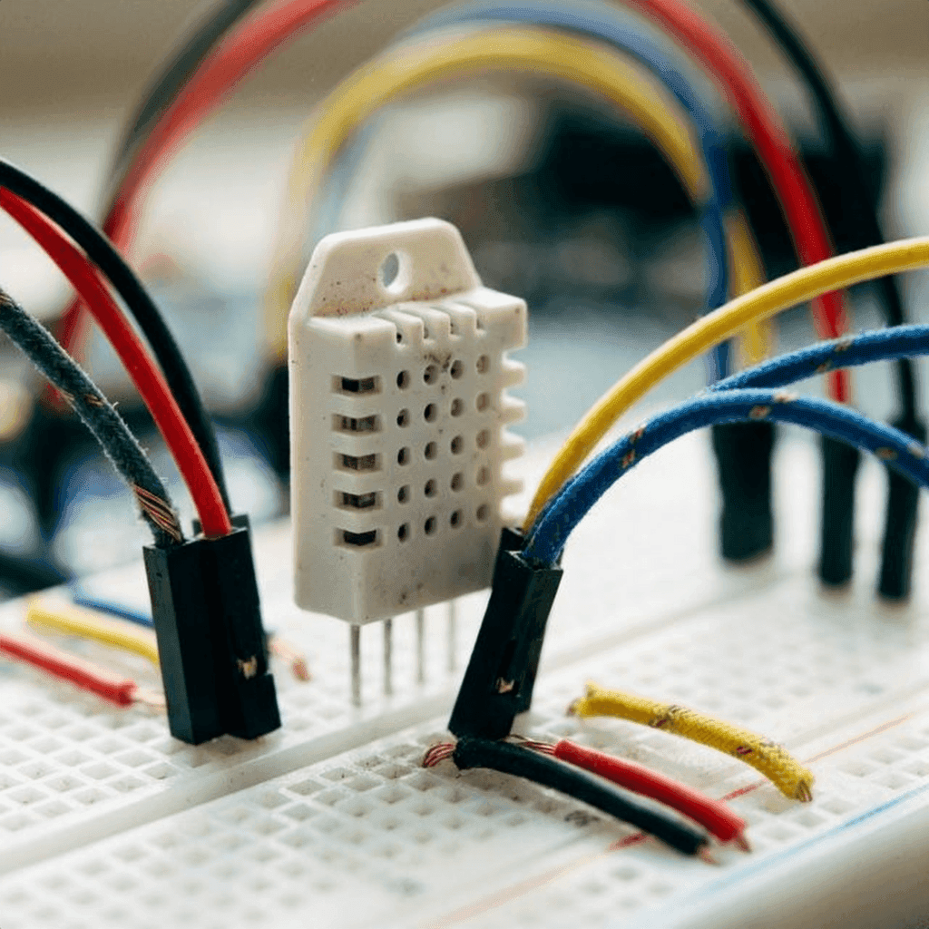
We are connecting the DHT22 sensor to measure our environment and an OLED screen to give us immediate local feedback.
Pro Tip: The ESP32 3.3V regulator can get hot if you pull too much current. For the OLED and sensors, it’s usually fine, but if you add relays or motors, use an external power supply.
This is where your software skills pay off. But beware: embedded C++ is not TypeScript. There is no garbage collector. Memory leaks don’t slow you down; they crash your device.
We will use PlatformIO instead of the Arduino IDE. The file structure and dependency management (via platformio.ini) are far superior for complex projects.
platformio.ini ConfigurationFirst, let’s define our environment and dependencies. We need libraries for the sensor, the display, and the MQTT client.
[env:esp32dev]
platform = espressif32
board = esp32dev
framework = arduino
monitor_speed = 115200
upload_speed = 921600
lib_deps =
    adafruit/Adafruit Unified Sensor @ ^1.1.9
    adafruit/DHT sensor library @ ^1.4.4
    adafruit/Adafruit GFX Library @ ^1.11.5
    adafruit/Adafruit SSD1306 @ ^2.5.7
knolleary/PubSubClient @ ^2.8config.hNever hardcode credentials in your main logic. We separate them here. In a real production environment, these would be injected during the build process or stored in NVS (Non-Volatile Storage).
#ifndef CONFIG_H
#define CONFIG_H

const char* SSID = "YOUR_WIFI_SSID";
const char* PASSWORD = "YOUR_WIFI_PASSWORD";

// MQTT Broker (Using a public test broker for this example, use AWS IoT in prod)
const char* MQTT_SERVER = "test.mosquitto.org";
const int MQTT_PORT = 1883; // Use 8883 for SSL/TLS
const char* MQTT_TOPIC_PUB = "technochips/device/data";
const char* MQTT_TOPIC_SUB = "technochips/device/command";

#endifmain.cppWe need to implement a non-blocking loop. The delay() function is the enemy. It floods the CPU and prevents network tasks from running. Instead, we use millis() to track time.
This pattern is essentially a manual event loop—something JavaScript developers should recognize immediately.
#include <Arduino.h>
#include <WiFi.h>
#include <PubSubClient.h>
#include <Adafruit_Sensor.h>
#include <DHT.h>
#include <Wire.h>
#include <Adafruit_GFX.h>
#include <Adafruit_SSD1306.h>
#include "config.h"

// Hardware Definitions
#define DHTPIN 4
#define DHTTYPE DHT22
#define SCREEN_WIDTH 128
#define SCREEN_HEIGHT 64

// Objects
DHT dht(DHTPIN, DHTTYPE);
WiFiClient espClient;
PubSubClient client(espClient);
Adafruit_SSD1306 display(SCREEN_WIDTH, SCREEN_HEIGHT, &Wire, -1);

// Variables for Non-Blocking Loop
unsigned long lastMsg = 0;
const long interval = 5000; // Send data every 5 seconds

void setup_wifi() {
  delay(10);
  Serial.println();
  Serial.print("Connecting to ");
  Serial.println(SSID);

  WiFi.begin(SSID, PASSWORD);

  while (WiFi.status() != WL_CONNECTED) {
    delay(500);
    Serial.print(".");
  }

  Serial.println("");
  Serial.println("WiFi connected");
  Serial.println("IP address: ");
  Serial.println(WiFi.localIP());
}

void callback(char* topic, byte* payload, unsigned int length) {
  Serial.print("Message arrived [");
  Serial.print(topic);
  Serial.print("] ");
  for (int i = 0; i < length; i++) {
    Serial.print((char)payload[i]);
  }
  Serial.println();
}

void reconnect() {
  while (!client.connected()) {
    Serial.print("Attempting MQTT connection...");
    // Create a random client ID
    String clientId = "ESP32Client-";
    clientId += String(random(0xffff), HEX);

    // Attempt to connect with LWT (Last Will and Testament)
    // If this device dies unexpectedly, the broker will publish "offline" to the status topic
    if (client.connect(clientId.c_str(), NULL, NULL, "technochips/device/status", 1, true, "offline")) {
      Serial.println("connected");
      // Publish "online" status (retained)
      client.publish("technochips/device/status", "online", true);
      client.subscribe(MQTT_TOPIC_SUB);
    } else {
      Serial.print("failed, rc=");
      Serial.print(client.state());
      Serial.println(" try again in 5 seconds");
      delay(5000);
    }
  }
}

void setup() {
  Serial.begin(115200);

  // Initialize Sensor
  dht.begin();

  // Initialize Display
  if(!display.begin(SSD1306_SWITCHCAPVCC, 0x3C)) {
    Serial.println(F("SSD1306 allocation failed"));
    for(;;);
  }
  display.display();
  delay(2000);
  display.clearDisplay();

  setup_wifi();
  client.setServer(MQTT_SERVER, MQTT_PORT);
  client.setCallback(callback);
}

void loop() {
  if (!client.connected()) {
    reconnect();
  }
  client.loop(); // Keeps the MQTT connection alive

  unsigned long now = millis();
  if (now - lastMsg > interval) {
    lastMsg = now;

    // Read Data
    float h = dht.readHumidity();
    float t = dht.readTemperature();

    if (isnan(h) || isnan(t)) {
      Serial.println("Failed to read from DHT sensor!");
      return;
    }

    // Create JSON Payload
    String payload = "{";
    payload += "\"temperature\":";
    payload += t;
    payload += ", \"humidity\":";
    payload += h;
    payload += "}";

    Serial.print("Publishing message: ");
    Serial.println(payload);

    client.publish(MQTT_TOPIC_PUB, (char*) payload.c_str());

    // Update Display
    display.clearDisplay();
    display.setTextSize(1);
    display.setTextColor(SSD1306_WHITE);

    display.setCursor(0,0);
    display.println("IoT Monitor");

    display.setTextSize(2);
    display.setCursor(0,20);
    display.print(t);
    display.print(" C");

    display.setCursor(0,45);
    display.print(h);
    display.print(" %");

    display.display();
  }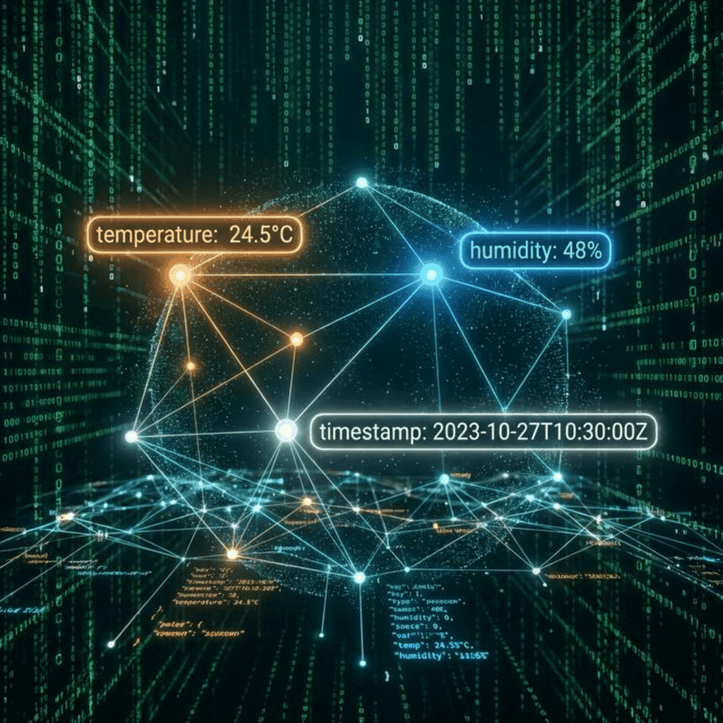
}The code significantly constructs a JSON payload. The structure is simple:
{
  "temperature": 24.5,
  "humidity": 48.0
}
This standardization is crucial. By sending structured JSON, we ensure that any subscriber—be it a Python script, a Node.js backend, or indeed an AWS Lambda function—can parse and use this data without knowing the specifics of the hardware that sent it.
Let’s pause the coding for a moment to understand why MQTT is so resilient. It offers features that HTTP simply cannot match without massive overhead.
MQTT defines three levels of assurance for message delivery. This is a contract between the sender and the receiver (or broker).
QoS 0: At most once
QoS 1: At least once
QoS 2: Exactly once
In our firmware code above, client.publish() defaults to QoS 0. If we were building a medical device, we would surely upgrade to QoS 1 or 2.
You might have noticed this line in the reconnect() function:
if (client.connect(clientId.c_str(), NULL, NULL, "technochips/device/status", 1, true, "offline"))This is LWT. It tells the broker: “If I disconnect ungracefully (crash, power loss, network failure) and don’t send a DISCONNECT packet, please publish ‘offline’ to the technochips/device/status topic on my behalf.”
This is how dashboards know a device is down instantly, without polling. It’s a game-changer for system reliability.
There is an old joke: The “S” in IoT stands for Security.
Most hobby projects skip this. We effectively cannot. If you are deploying a device into someone’s home or a factory floor, you must secure the channel.
The basic MQTT code above uses unencrypted TCP (Port 1883). Anyone with Wireshark on the same network can see your data.
To fix this, we need TLS/SSL (Transport Layer Security). This involves:
In the ESP32 code, this changes the connection setup slightly using WiFiClientSecure:
WiFiClientSecure espClient;

// Load certificates from PROGMEM or SPIFFS
const char* root_ca = \
"-----BEGIN CERTIFICATE-----\n" \
"MIIDQTCCAimgAwIBAgITBmyfz5m/jAo54vB4ikPmljZbyjANBgkqhkiG9w0BAQsF\n" \
"ADA5MQswCQYDVQQGEwJVUzEPMA0GA1UEChMGQW1hem9uMRkwFwYDVQQDExBBbWF6\n" \
"on... (rest of certificate)\n" \
"-----END CERTIFICATE-----\n";

void setup_security() {
  espClient.setCACert(root_ca);
  // espClient.setCertificate(client_cert); // Mutual Auth
  // espClient.setPrivateKey(private_key);  // Mutual Auth
}
This encryption ensures that even if the data packets are intercepted, they are computationally impossible to read.

Now that our device is shouting data into the void, let’s build something to catch it. We’ll create a simple Node.js server that acts as a bridge between MQTT and a WebSocket frontend.
mqtt packagews package (for WebSockets)server.js/*
* Simple IoT Backend Bridge
* Listens to MQTT and broadcasts via WebSocket
*/
const mqtt = require('mqtt');
const WebSocket = require('ws');
// MQTT Configuration
const MQTT_BROKER = 'mqtt://test.mosquitto.org';
const TOPIC_DATA = 'technochips/device/data';
const TOPIC_STATUS = 'technochips/device/status';
// WebSocket Server
const wss = new WebSocket.Server({ port: 8080 });
// MQTT Client
const client = mqtt.connect(MQTT_BROKER);
client.on('connect', () => {
console.log('Connected to MQTT Broker');
client.subscribe([TOPIC_DATA, TOPIC_STATUS], (err) => {
if (!err) {
console.log(`Subscribed to: ${TOPIC_DATA}, ${TOPIC_STATUS}`);
}
});
});
client.on('message', (topic, message) => {
const payload = message.toString();
console.log(`Received [${topic}]: ${payload}`);
// Broadcast to all connected WebSocket clients
wss.clients.forEach((ws) => {
if (ws.readyState === WebSocket.OPEN) {
ws.send(JSON.stringify({
type: topic === TOPIC_DATA ? 'telemetry' : 'status',
topic: topic,
payload: JSON.parse(payload),
timestamp: new Date().toISOString()
}));
}
});
});
wss.on('connection', (ws) => {
console.log('New Client Connected');
ws.send(JSON.stringify({ type: 'info', message: 'Connected to IoT Bridge' }));
});
console.log('WebSocket Server running on port 8080');This script creates a real-time pipeline. As soon as the ESP32 publishes a temperature reading:
What good is data if you can’t see it?
We can subscribe to our MQTT topic using a tool like MQTT Explorer for debugging, but for a user, we need a dashboard.
In a professional stack, you might ingest this data into AWS IoT Core, route it via a Rule to AWS Timestream, and visualize it with Grafana.
For our example, let’s imagine the data flow to a custom React dashboard.
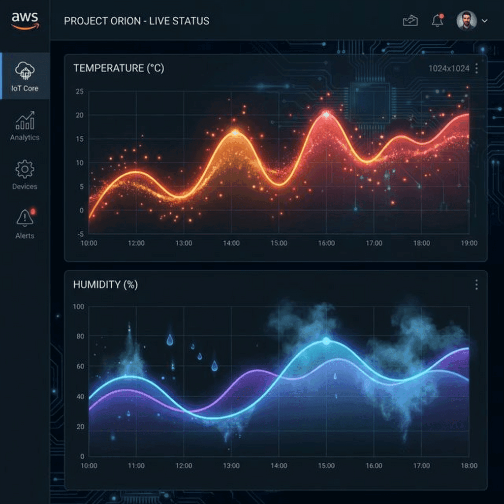
Dashboard.jsx)We’ll use recharts for visualization.
import React, { useEffect, useState } from 'react';
import { LineChart, Line, XAxis, YAxis, Tooltip, ResponsiveContainer } from 'recharts';

const Dashboard = () => {
    const [data, setData] = useState([]);
    const [status, setStatus] = useState('offline');

    useEffect(() => {
        const ws = new WebSocket('ws://localhost:8080');

        ws.onmessage = (event) => {
            const message = JSON.parse(event.data);

            if (message.type === 'telemetry') {
                setData(prev => {
                    const newData = [...prev, {
                        time: new Date().toLocaleTimeString(),
                        temp: message.payload.temperature,
                        humid: message.payload.humidity
                    }];
                    // Keep only last 20 readings
                    return newData.slice(-20);
                });
            } else if (message.type === 'status') {
                setStatus(message.payload); // 'online' or 'offline' via LWT
            }
        };

        return () => ws.close();
    }, []);

    return (
        <div className="p-6 bg-slate-900 min-h-screen text-white">
            <header className="flex justify-between items-center mb-8">
                <h1 className="text-3xl font-bold">IoT Environment Monitor</h1>
                <span className={`px-4 py-1 rounded-full ${status === 'online' ? 'bg-green-500' : 'bg-red-500'}`}>
                    {status.toUpperCase()}
                </span>
            </header>

            <div className="grid grid-cols-1 md:grid-cols-2 gap-6">
                <div className="bg-slate-800 p-4 rounded-xl shadow-lg">
                    <h2 className="text-xl mb-4 text-orange-400">Temperature (°C)</h2>
                    <div className="h-64">
                        <ResponsiveContainer width="100%" height="100%">
                            <LineChart data={data}>
                                <XAxis dataKey="time" stroke="#94a3b8" />
                                <YAxis stroke="#94a3b8" />
                                <Tooltip contentStyle={{ backgroundColor: '#1e293b', border: 'none' }} />
                                <Line type="monotone" dataKey="temp" stroke="#f97316" strokeWidth={2} dot={false} />
                            </LineChart>
                        </ResponsiveContainer>
                    </div>
                </div>

                <div className="bg-slate-800 p-4 rounded-xl shadow-lg">
                    <h2 className="text-xl mb-4 text-blue-400">Humidity (%)</h2>
                    <div className="h-64">
                        <ResponsiveContainer width="100%" height="100%">
                            <LineChart data={data}>
                                <XAxis dataKey="time" stroke="#94a3b8" />
                                <YAxis stroke="#94a3b8" />
                                <Tooltip contentStyle={{ backgroundColor: '#1e293b', border: 'none' }} />
                                <Line type="monotone" dataKey="humid" stroke="#3b82f6" strokeWidth={2} dot={false} />
                            </LineChart>
                        </ResponsiveContainer>
                    </div>
                </div>
            </div>
        </div>
    );
};

export default Dashboard;
This is a complete, functioning dashboard. It listens for the LWT “offline” message to turn the status badge red, and it updates the charts in real-time as new telemetry flows in.
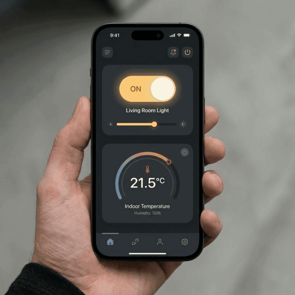
In 2026, users expect to control their devices from their phones.
The communication flow reverses here. The phone app publishes a message to technochips/device/command, for example: {"relay": "ON"}.
The ESP32, which is subscribed to this topic, receives the message instantaneously (thanks to the persistent TCP connection of MQTT) and flips the GPIO pin.
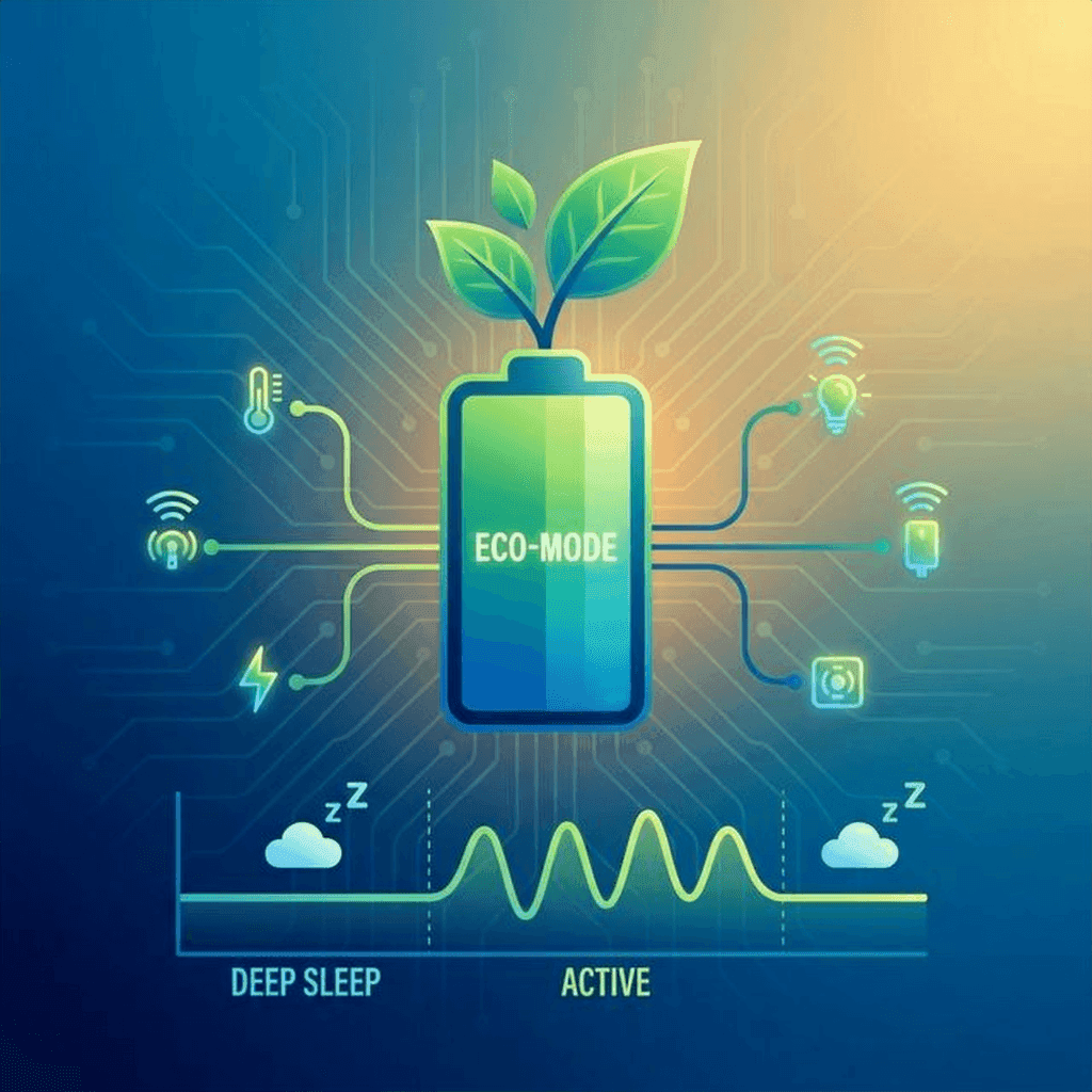
If your device is plugged into the wall, power is cheap. If it’s on a battery, every milliamp-hour counts.
The ESP32 is power-hungry when WiFi is on (~150mA). A standard 2000mAh LiPo battery would last less than a day.
To fix this, we use Deep Sleep.
Deep sleep shuts down the CPU, WiFi, and Bluetooth, leaving only the RTC (Real Time Clock) running. The power consumption drops to roughly 10µA.
The workflow becomes:
// Sleep for 10 minutes (in microseconds)
esp_sleep_enable_timer_wakeup(10 * 60 * 1000000);
esp_deep_sleep_start();
This simple change can extend battery life from 12 hours to 6 months.
You’ve shipped your device to customers. You find a bug. Now what?
You can’t ask them to plug in a USB cable. You need OTA.
OTA allows the device to download a new binary file from a server and flash itself.
api.technochips.org/firmware/latest)..bin file.This is the holy grail of embedded development. It turns static hardware into evolving software products.

Hardware bugs are harder to debug than software bugs because you can’t always just “step through” them. Here are the most common issues beginners face.
Symptom: The ESP32 restarts randomly, especially when connecting to WiFi. You see “Brownout detector was triggered” in the serial monitor. Cause: The WiFi chip draws a sudden spike of current, causing the voltage to dip below 2.5V. Fix: Add a 10µF or 100µF capacitor across the VCC and GND pins of your module. Better yet, get a better power supply. USB ports on laptops are notoriously weak.
Symptom: Connection fails repeatedly. Cause: Network firewall or incorrect credentials. Fix:
Symptom: dht.readTemperature() returns nan (Not a Number).
Cause: Timing issue or bad wiring.
Fix:
Symptom: “A fatal error occurred: Failed to connect to ESP32: Timed out…”. Cause: The ESP32 needs to be in Bootloader mode. Fix: Hold the BOOT button on the DevKit while the upload starts. Release it once you see the “Connecting…” message change to “Writing…”.
Our mosquitto.org test broker is great for prototypes, but it won’t scale to 10,000 devices. For that, we need a managed service like AWS IoT Core.
As software developers, we are used to AWS. IoT Core is just another service, but with a different protocol.
In AWS, every device is a “Thing.” It has a:
Here is a restrictive policy that allows a device to only publish to its own topic. This is crucial for security.
{
  "Version": "2012-10-17",
  "Statement": [
    {
      "Effect": "Allow",
      "Action": "iot:Connect",
      "Resource": "arn:aws:iot:us-east-1:123456789012:client/ESP32-*"
    },
    {
      "Effect": "Allow",
      "Action": "iot:Publish",
      "Resource": "arn:aws:iot:us-east-1:123456789012:topic/technochips/device/data"
    }
  ]
}This is where the magic happens. You can write SQL-like queries to route incoming MQTT messages to other AWS services.
Query:
SELECT temperature, humidity, timestamp() as time FROM 'technochips/device/data' WHERE temperature > 30Action:
This integration turns your hardware into a native part of your cloud infrastructure.
After running your device for a week, you’ll have thousands of data points. Let’s act like data scientists and analyze the thermal performance of our room.
We’ll use Pandas and Matplotlib. Assuming you saved your logs to a CSV or pulled them from AWS Timestream:
import pandas as pd
import matplotlib.pyplot as plt
import seaborn as sns

# Load the data
df = pd.read_csv('sensor_logs.csv')

# Convert timestamp string to datetime objects
df['timestamp'] = pd.to_datetime(df['timestamp'])

# Set timestamp as index for easier resampling
df.set_index('timestamp', inplace=True)

# Resample to hourly averages to smooth out noise
hourly_avg = df.resample('H').mean()

# Calculate statistics
max_temp = df['temperature'].max()
min_temp = df['temperature'].min()
avg_humidity = df['humidity'].mean()

print(f"Max Temp: {max_temp}°C")
print(f"Min Temp: {min_temp}°C")
print(f"Avg Humidity: {avg_humidity:.1f}%")

# Correlation Analysis
correlation = df['temperature'].corr(df['humidity'])
print(f"Correlation between Temp and Humidity: {correlation:.2f}")

# Plotting
plt.figure(figsize=(12, 6))
sns.set_theme(style="darkgrid")

# Create dual-axis plot
ax1 = plt.gca()
ax2 = ax1.twinx()

sns.lineplot(data=hourly_avg, x=hourly_avg.index, y='temperature', ax=ax1, color='orange', label='Temperature')
sns.lineplot(data=hourly_avg, x=hourly_avg.index, y='humidity', ax=ax2, color='blue', label='Humidity')

ax1.set_ylabel('Temperature (°C)', color='orange')
ax2.set_ylabel('Humidity (%)', color='blue')
plt.title('Weekly Environmental Trends')

plt.show()You might discover:
This feedback loop—build, measure, analyze, improve—is the core of engineering, whether software or hardware.
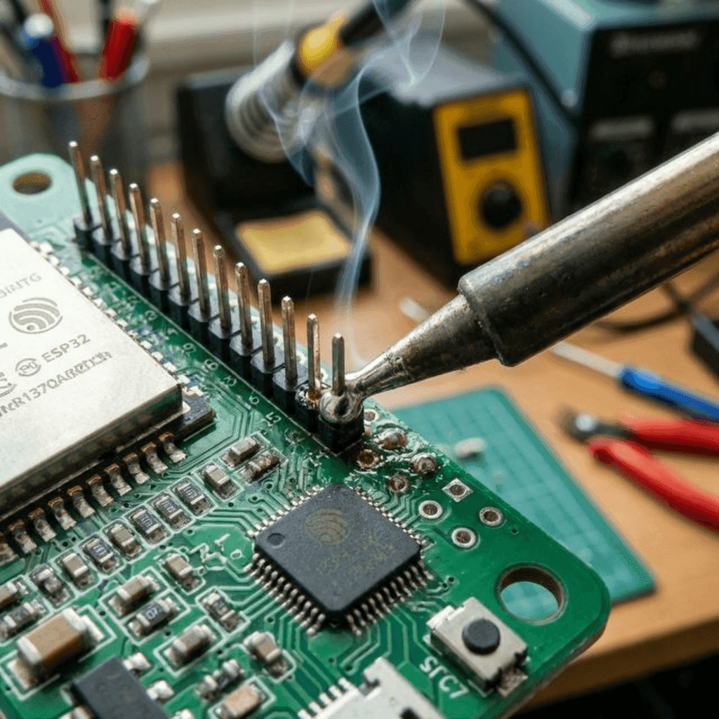
The breadboard is where ideas are born, but it’s not where they live.
To make this a “finished” product, we move from jumper wires to a custom PCB (as we learned in Post 9) and a 3D-printed enclosure.
Soldering headers onto the final board gives us a robust, vibration-resistant connection. It’s a permanent commitment to the circuit you’ve designed.
We have built a system that spans the entire technology stack.
We wrote C++ that talks to silicon. We sent packets across the airwaves. We routed data through the cloud. We visualized it on a screen.
This is the power of the Full Stack Hardware Developer. You are no longer constrained by the browser window or the server rack. You have the power to instrument the world, to gather its data, and to affect it physically.
The journey doesn’t end here. It only gets deeper. FPGAs, RTOS, custom silicon… the rabbit hole is infinite.
But for now, look at your desk. That little board, blinking away, sending its temperature to the cloud? That’s magic. And you built it.
See you in the next build.
For those attempting the full build, here is the robust version of the main loop, including error handling and reconnection logic often skipped in tutorials.
/*
 * Full Production-Ready IoT Monitor
 * Author: Rahul
 * Date: 2026-02-17
 * License: MIT
 */

#include <Arduino.h>
#include <WiFi.h>
#include "time.h"
#include <PubSubClient.h>
#include <Adafruit_Sensor.h>
#include <DHT.h>
#include <Wire.h>
#include <Adafruit_GFX.h>
#include <Adafruit_SSD1306.h>
#include "config.h"

// Hardware Definitions
#define DHTPIN 4
#define DHTTYPE DHT22
#define SCREEN_WIDTH 128
#define SCREEN_HEIGHT 64

// Objects
DHT dht(DHTPIN, DHTTYPE);
WiFiClient espClient;
PubSubClient client(espClient);
Adafruit_SSD1306 display(SCREEN_WIDTH, SCREEN_HEIGHT, &Wire, -1);

// Variables for Non-Blocking Loop
unsigned long lastMsg = 0;
const long interval = 5000; // Send data every 5 seconds

// NTP Server settings for accurate timestamps
const char* ntpServer = "pool.ntp.org";
const long  gmtOffset_sec = 0;
const int   daylightOffset_sec = 3600;

void printLocalTime(){
  struct tm timeinfo;
  if(!getLocalTime(&timeinfo)){
    Serial.println("Failed to obtain time");
    return;
  }
  Serial.println(&timeinfo, "%A, %B %d %Y %H:%M:%S");
}

void setup_wifi() {
  delay(10);
  Serial.println();
  Serial.print("Connecting to ");
  Serial.println(SSID);

  WiFi.begin(SSID, PASSWORD);

  while (WiFi.status() != WL_CONNECTED) {
    delay(500);
    Serial.print(".");
  }

  Serial.println("");
  Serial.println("WiFi connected");
  Serial.println("IP address: ");
  Serial.println(WiFi.localIP());

  // Init and get the time
  configTime(gmtOffset_sec, daylightOffset_sec, ntpServer);
  printLocalTime();
}

void callback(char* topic, byte* payload, unsigned int length) {
  Serial.print("Message arrived [");
  Serial.print(topic);
  Serial.print("] ");
  String messageTemp;
  for (int i = 0; i < length; i++) {
    Serial.print((char)payload[i]);
    messageTemp += (char)payload[i];
  }
  Serial.println();

  // Switch on the LED if an 1 was received as first character
  if ((char)payload[0] == '1') {
    // digitalWrite(BUILTIN_LED, LOW);   // Turn the LED on (Note that LOW is the voltage level
    // but actually the LED is on; this is true for ESP-01)
  } else {
    // digitalWrite(BUILTIN_LED, HIGH);  // Turn the LED off by making the voltage HIGH
  }
}

void reconnect() {
  while (!client.connected()) {
    Serial.print("Attempting MQTT connection...");
    String clientId = "ESP32Client-";
    clientId += String(random(0xffff), HEX);

    // Attempt to connect with LWT
    if (client.connect(clientId.c_str(), NULL, NULL, "technochips/device/status", 1, true, "offline")) {
      Serial.println("connected");
      client.publish("technochips/device/status", "online", true);
      client.subscribe(MQTT_TOPIC_SUB);
    } else {
      Serial.print("failed, rc=");
      Serial.print(client.state());
      Serial.println(" try again in 5 seconds");
      delay(5000);
    }
  }
}

// Robust Reconnection Strategy
void ensureNetwork() {
    if (WiFi.status() != WL_CONNECTED) {
        Serial.println("WiFi Lost. Reconnecting...");
        WiFi.disconnect();
        WiFi.reconnect();

        // Wait up to 10 seconds for WiFi
        int attempts = 0;
        while (WiFi.status() != WL_CONNECTED && attempts < 20) {
            delay(500);
            Serial.print(".");
            attempts++;
        }
    }

    if (WiFi.status() == WL_CONNECTED && !client.connected()) {
        reconnect();
    }
}

void setup() {
  Serial.begin(115200);

  dht.begin();

  if(!display.begin(SSD1306_SWITCHCAPVCC, 0x3C)) {
    Serial.println(F("SSD1306 allocation failed"));
    for(;;);
  }
  display.display();
  delay(2000);
  display.clearDisplay();

  setup_wifi();
  client.setServer(MQTT_SERVER, MQTT_PORT);
  client.setCallback(callback);
}

void loop() {
    ensureNetwork();
    client.loop();

    // Heartbeat for debugging
    static unsigned long lastHeartbeat = 0;
    if (millis() - lastHeartbeat > 60000) {
        lastHeartbeat = millis();
        Serial.println("System Healthy. Heap: " + String(ESP.getFreeHeap()));
    }


    unsigned long now = millis();
    if (now - lastMsg > interval) {
      lastMsg = now;

      float h = dht.readHumidity();
      float t = dht.readTemperature();

      if (isnan(h) || isnan(t)) {
        Serial.println("Failed to read from DHT sensor!");
        return;
      }

      String payload = "{";
      payload += "\"temperature\":";
      payload += t;
      payload += ", \"humidity\":";
      payload += h;
      payload += "}";

      Serial.print("Publishing message: ");
      Serial.println(payload);

      client.publish(MQTT_TOPIC_PUB, (char*) payload.c_str());

      display.clearDisplay();
      display.setTextSize(1);
      display.setTextColor(SSD1306_WHITE);
      display.setCursor(0,0);
      display.println("IoT Monitor");
      display.setTextSize(2);
      display.setCursor(0,20);
      display.print(t);
      display.print(" C");
      display.setCursor(0,45);
      display.print(h);
      display.print(" %");
      display.display();
    }
}We started this series by looking at a simple circuit. Today, we’ve built a system that bridges the gap between the physical world and the digital cloud.
IoT isn’t just about “connecting things”; it’s about making those connections meaningful, secure, and resilient. By applying the software principles you already know—structuring data, securing channels, and building for scale—you’ve transformed a raw microcontroller into a production-ready product.
What’s next? Take this code and expand it. Add more sensors, build a more complex dashboard, or even try your hand at custom enclosure design. The hardware world is now your playground.
Thanks for joining me on Day 10. Stay curious, keep building, and I’ll see you in the next post.

WiFi barely reaches your driveway. LoRa reaches the next town. Master the SX1278 module, Chirp Spread Spectrum physics, and build a 5km range sensor network.
Read More →
Stop polling your server every 5 seconds. Learn why Professional IoT uses MQTT. Master Pub/Sub architecture, QoS levels, Retained Messages, and Last Will & Testament.
Read More →
Run your IoT sensors for a year on a single coin cell. Mastering ESP8266 Deep Sleep, RTC Memory persistence, and the hardware hacks needed to achieve 20uA power consumption.
Read More →