From Code to Reality: Building a Production-Grade IoT Device
A complete, end-to-end guide on building a secure, scalable IoT device using ESP32, MQTT, and AWS IoT Core. We bridge the gap between software logic and hardware reality.
Read More →
* SYSTEM.NOTICE: Affiliate links support continued laboratory research.
For the past 30 days, we have been “Learning”. We learned Ohm’s Law. We learned how a Transistor amplifies current. We learned how I2C moves bits between chips. We learned how HTTP requests traverse the globe. But “knowing” is not “building”. Engineering is the art of Integration. It is the ability to take ten disparate, conflicting components—some that want , some that want , some that block code, some that need microseconds—and making them dance together in perfect unison.
Today, we stop being “Hobbyists” tinkering with breadboards. Today, we become Systems Engineers.
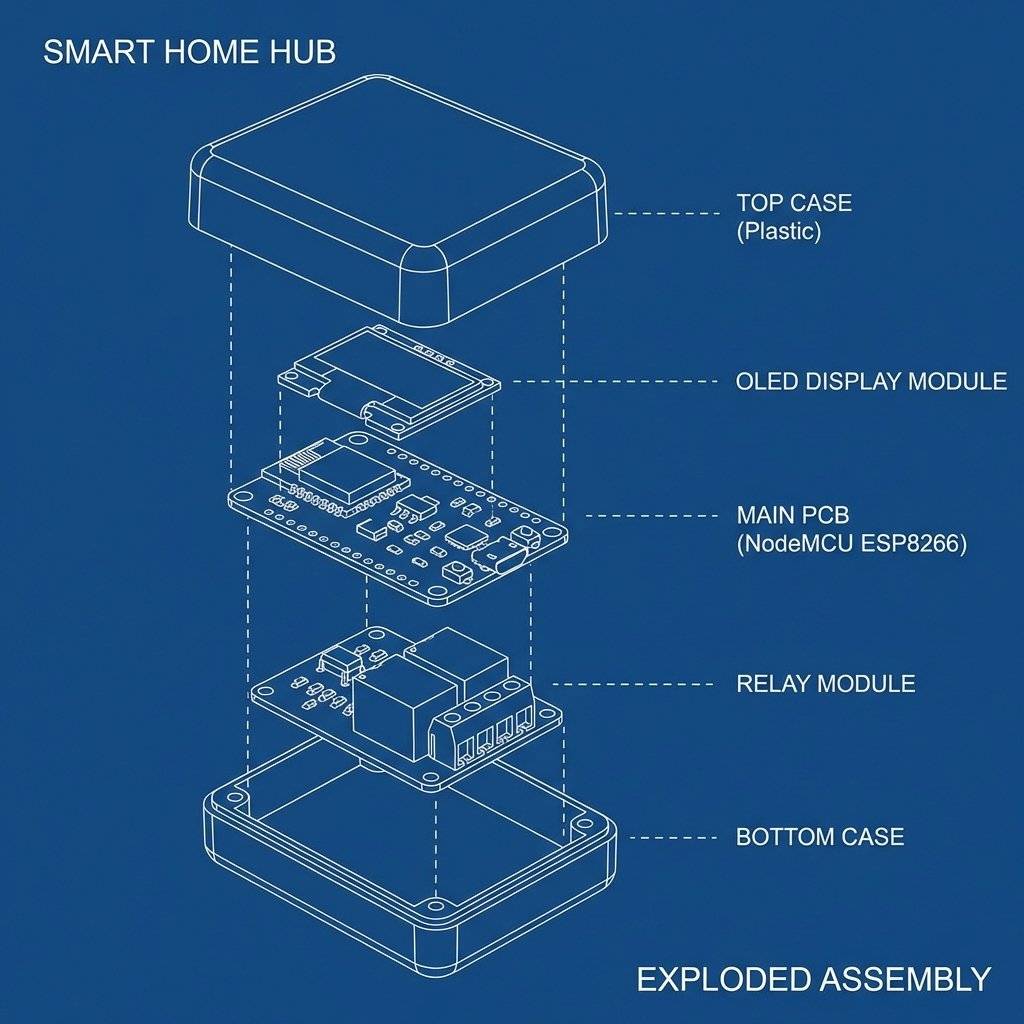
We are going to build the technochips Smart Hub. This is not a toy. This is a prototype for a commercial product.
The Mission Specification:
Before we write a single line of code, we must understand the “System”.
A novice writes a loop() that reads a sensor, then updates the screen, then checks Wi-Fi.
This is Sequential Architecture. It is fatal for IoT.
Why?
If you sequence these, your User Interface (Web Dashboard) will lag. When a user taps “Fan ON” on their phone, the ESP8266 might be busy drawing pixels on the OLED. The TCP packet will be dropped. The user will think “This device is broken.”
The Solution: The Non-Blocking Super-Loop
We will implement a Cooperative Multitasking Scheduler. We will slice our timeline into millisecond-sized chunks. The CPU will “poll” tasks continuously, only executing them when their specific time slot arrives. We will use the millis() hardware timer as our master clock.
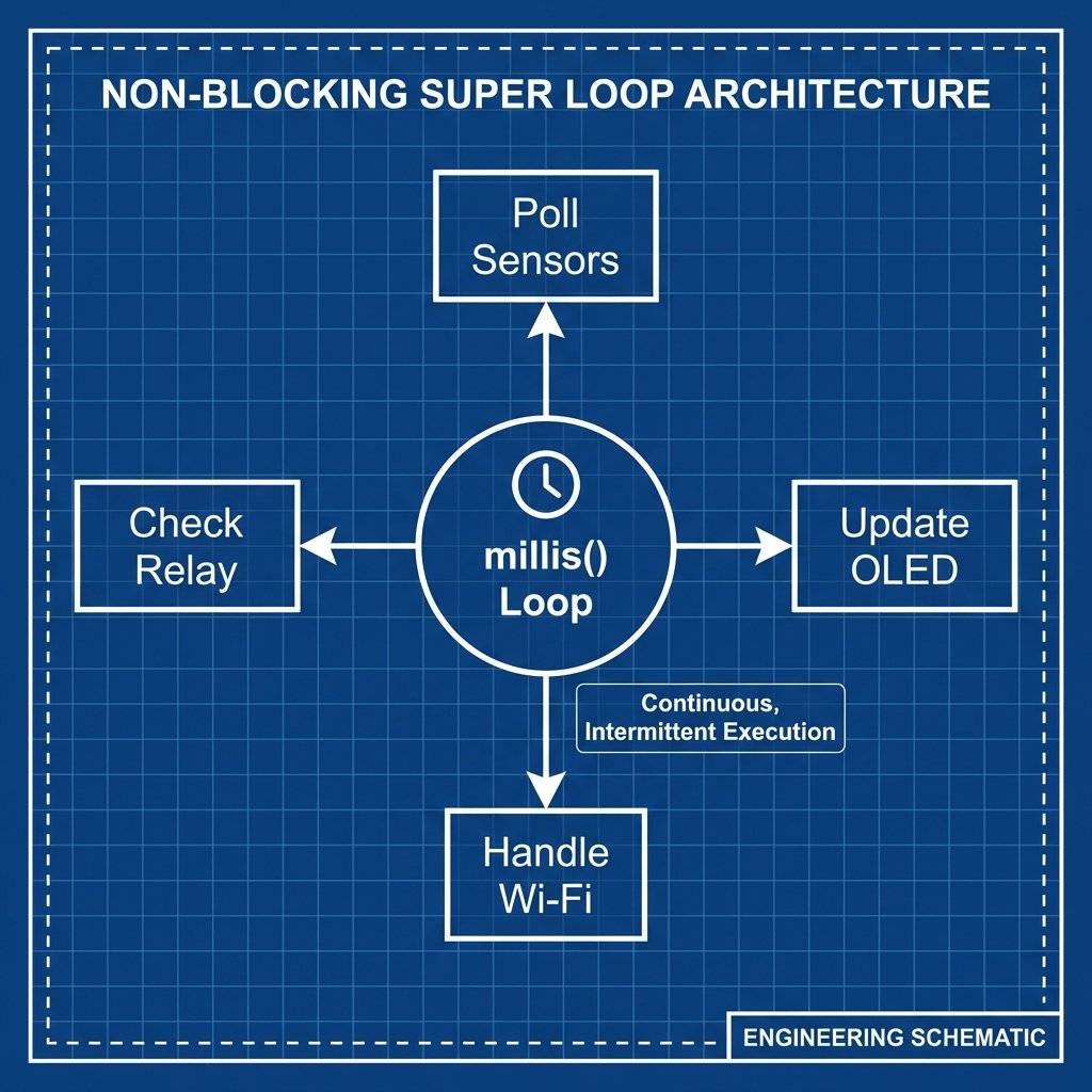
This architecture separates our concerns into three layers:
A valid question is: “Why not use FreeRTOS?” The ESP8266 does run a lightweight RTOS (Real-Time Operating System) in the background to manage Wi-Fi. However, adding user-level threads consumes stack memory per task.
We use millis() for coarse timing (ms level). But what if the DHT11 needs microsecond timing?
The DHT11 library uses ISRs. It halts the CPU for to catch the rising edge of a signal.
Critical Risk: If your Wi-Fi interrupts an ISR, the system crashes (WDT Reset).
Mitigation: noInterrupts() and interrupts() are used carefully around critical timing sections to ensure data integrity.
Why did we choose the ESP8266 ($3.50) over the ESP32 ($6.00)?
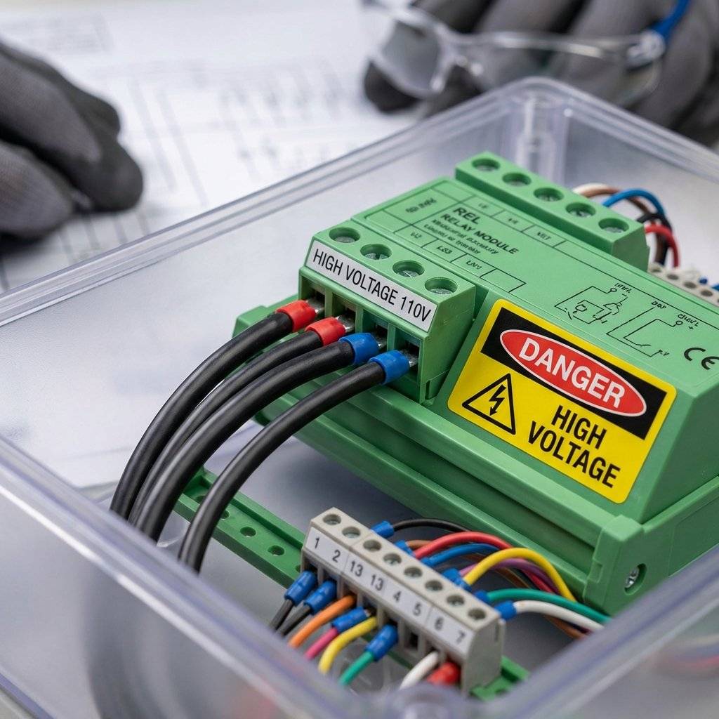
We are combining high-speed digital logic () with mains power control (). This requires a deep understanding of the physics involved.
You cannot connect a relay coil directly to an ESP8266 GPIO.
Since the current change () is near zero, the Voltage () spikes to hundreds of volts.
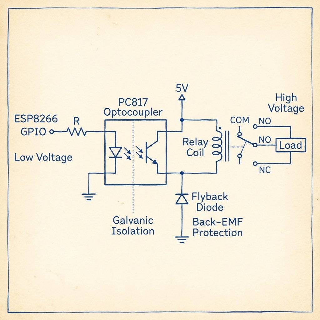
The Engineering Solution: We use a Relay Module with an onboard Optocoupler (PC817) and Flyback Diode.
There is Zero Electrical Connection between the High Voltage side and the Low Voltage ESP8266. This is Galvanic Isolation. It protects the CPU from noise and spikes.
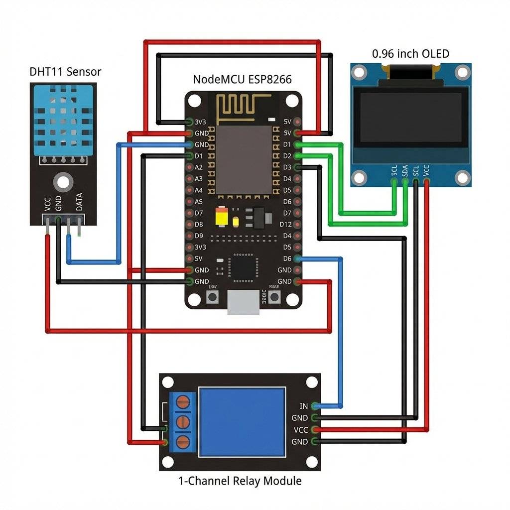
We are using the I2C Protocol (Inter-Integrated Circuit).
Clock Speed: (Fast Mode).
Pull-Up Resistors: Lines need resistors to pull HIGH.
Capacitance Trap: Long wires (>10cm) cause “shark fins” signals.
The Fix: Keep wires short. If you see “snow” or artifacts on the screen, your rise-times are too slow.
The ESP8266 is a current-hungry beast.
Correct wiring is non-negotiable for system stability.
DANGER: KILLS. If you are switching a real load (Lamp/Heater):
How long will this hub last?
We are effectively writing a small Operating System. The ESP8266 has a Harvard Architecture (Modified). It has distinct Instruction Memory (Flash) and Data Memory (RAM).
A common rookie mistake is defining the HTML string like this:
String html = "<html>...</html>";
This puts the string in RAM. With a large dashboard, you will crash the chip (Stack Overflow).
PROGMEM keyword.
const char html[] PROGMEM = "<html>...</html>";
This forces the compiler to keep the data in Flash Memory (Instruction Store), leaving RAM totally free for the Stack.Reliability is our #1 goal. The ESP8266 hardware contains a “Watchdog”. It is a countdown timer. If the CPU does not reset this timer every ~3 seconds, the Watchdog assumes the code has crashed and Hard Resets the board.
delay(5000) causes WDT resets.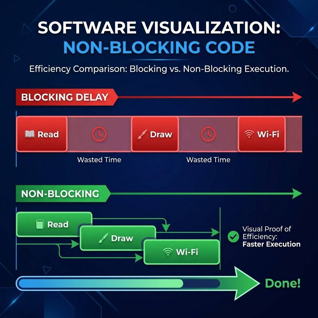
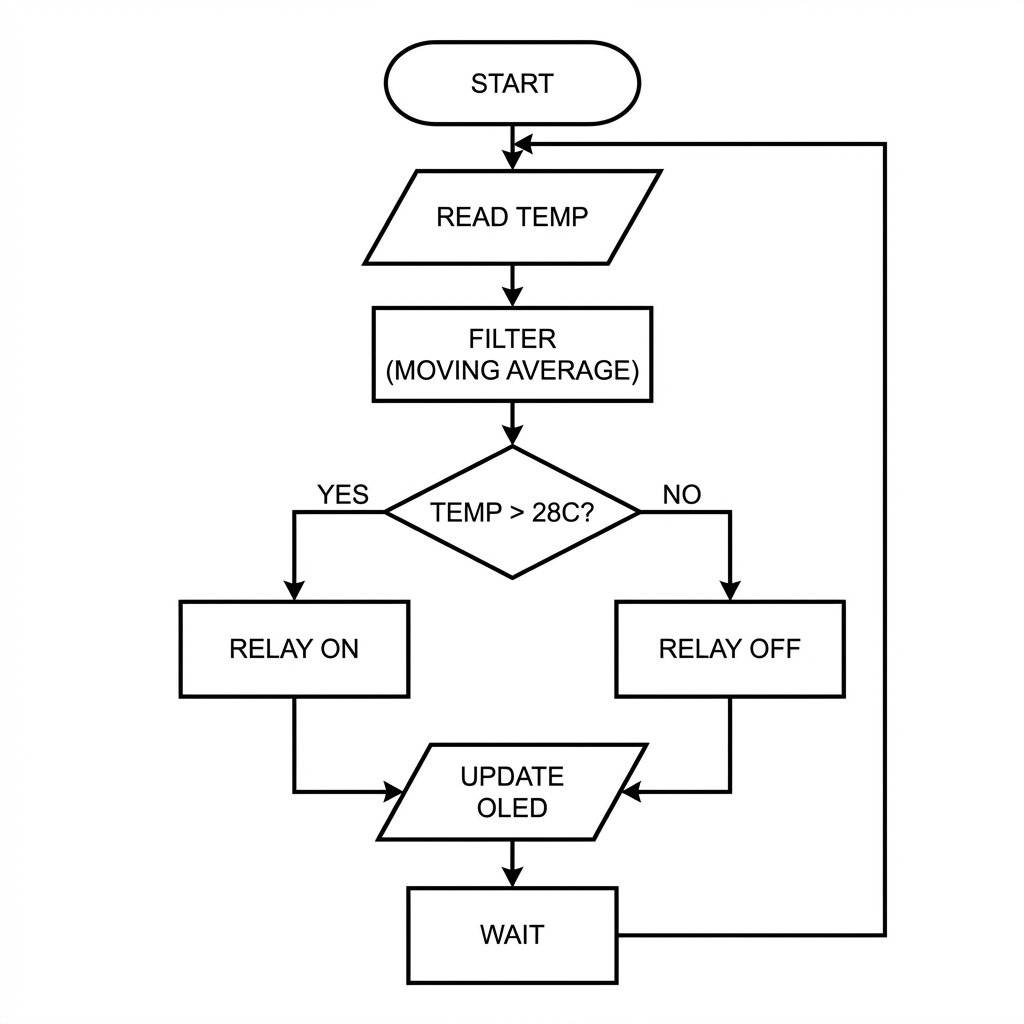
Sensors are noisy. Air turbulence causes the DHT11 to jitter.
23.1, 23.2, 23.1, 28.5 (Error), 23.2
If we use raw data, our Relay will “chatter” (Click-On-Click-Off).
We implement Digital Signal Processing (DSP): The Moving Average Filter.
We maintain a circular buffer of the last N readings.
This smooths out noise and rejects transient spikes.
The “Internet” in IoT is just HTTP. When your phone asks the hub for temperature, a complex dance occurs.
GET /temperature HTTP/1.1.When you send “24.5”, you aren’t just sending 4 bytes. You are sending a 1500-byte Ethernet Frame:
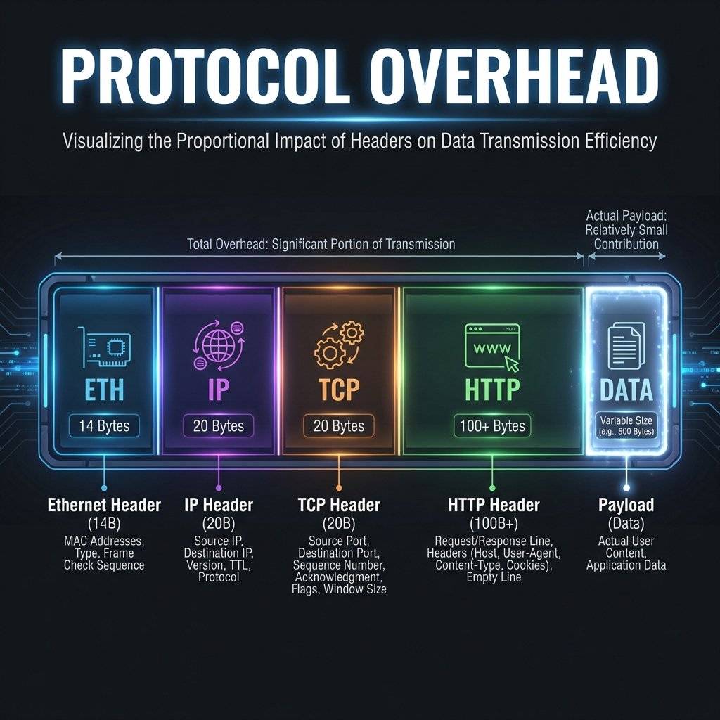
We send data as JSON: {"temp": 24.5}.
Size: 14 bytes per packet.
Binary Alternative: We could send a raw 4-byte float: $0x41C40000$.
Trade-off: JSON is readable by humans (High Maintainability). Binary is fast (High Efficiency). Since we have Wi-Fi bandwidth (Mbits), we prioritize Human Readability. If we were using LoRaWAN (bytes/hour), we would use binary.
Connecting a heater to the internet creates a vector for cyber-physical attacks.
You see const char* password = "My_Password"; in the code.
The Risk: If you upload this code to GitHub, bots will scrape your credentials in < 1 minute.
The Protection: Use a separate secrets.h file and add it to .gitignore. Never commit keys.
An ESP8266 has limited sockets (max 4). If a malicious actor opens 4 connections and keeps them open (“Slowloris Attack”), the hub becomes unresponsive.
client.stop().Our AJAX requests come from the same origin (the ESP itself).
But if a malicious website tries to fetch('http://192.168.1.50/toggle'), the browser blocks it by default.
DO NOT add Access-Control-Allow-Origin: * headers unless you understand the risk. This header allows any website to toggle your fans.
The interface is not just a “page”. It is an Application. We use CSS3 Grid/Flexbox for layout and Vanilla JS for logic. No heavy frameworks (React/Vue) needed.
We want a “Dark Mode” aesthetic using Material Design principles.
Card: A unified container with drop shadows (box-shadow: 0 10px 30px rgba(0,0,0,0.5)).
Gauge: A CSS Conic Gradient (conic-gradient) that changes color dynamically based on temperature.
Feedback: CSS Transitions (transition: all 0.3s ease) to make button presses feel tactile.
The browser runs a minimal state machine:
State: Disconnected (Gray text).
Event: AJAX Success -> State: Connected (Green/Blue text).
Event: AJAX Timeout -> State: Offline (Red text).
This gives the user immediate feedback if the hub loses power, rather than just showing a frozen number.
Why use CSS Updates instead of replacing innerHTML?
Reflow: When you change the layout (width, height), the browser must recalculate the position of every pixel. This is CPU, battery, and time expensive.
Repaint: When you change the color or opacity, the browser just redraws the pixels in place.
Our Strategy: The Gauge uses conic-gradient. Changing the gradient is a Repaint. It is silky smooth (60fps) even on an old Android phone.
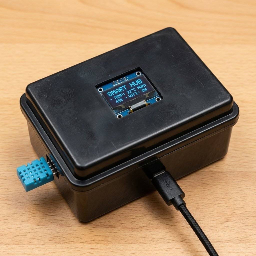
To go from “Prototype” to “Product”, we need a Bill of Materials (BoM) and an Assembly Process.
| Component | SKU | Cost | Notes |
|---|---|---|---|
| Microcontroller | NodeMCU v3 | $3.50 | The brain. |
| Display | 0.96” OLED I2C | $2.50 | White Pixel. |
| Sensor | DHT11 Module | $1.50 | Includes 10k pull-up. |
| Relay | 1-Ch Relay | $1.00 | With Optocoupler. |
| Power | PSU | $0.00 | Recycled Phone Charger. |
| Case | Project Box | $2.00 | ABS Plastic (Safety). |
| Total | $10.50 |
De-soldering: Remove header pins from modules if soldering wires directly for reliability.
Insulation: Use Heat Shrink Tubing on all exposed joints. Tape is for temporary fixes; Heat Shrink is for products.
Hot Glue: Secure the DHT11 and OLED to the case lid to prevent movement (Vibration testing).
Here is the complete, integrated firmware. It combines the millis() scheduler, ArduinoOTA, ESP8266WebServer, and SSD1306 logic.
/**
* Project: DeepMind SafeHome Hub (Capstone Edition)
* Author: TechnoChips
* Hardware: ESP8266, DHT11, SSD1306, $5\text{V}$ Relay
* License: MIT
*/
#include <ESP8266WiFi.h>
#include <ESP8266WebServer.h>
#include <ArduinoOTA.h>
#include <Wire.h>
#include <Adafruit_GFX.h>
#include <Adafruit_SSD1306.h>
#include <DHT.h>
// --- Configuration Constants ---
const char* ssid = "YOUR_WIFI_SSID";
const char* password = "YOUR_WIFI_PASS";
const char* ota_pass = "admin123";
#define RELAY_PIN 14 // GPIO 14 (D5) - Safe Pin
#define DHT_PIN 12 // GPIO 12 (D6) - Safe Pin
#define DHT_TYPE DHT11
// --- Objects ---
Adafruit_SSD1306 display(128, 64, &Wire, -1);
DHT dht(DHT_PIN, DHT_TYPE);
ESP8266WebServer server(80);
// --- Global State ---
float currentTemp = 0.0;
float currentHum = 0.0;
bool relayState = false;
unsigned long lastSensorRead = 0;
unsigned long lastDisplayUpdate = 0;
const long SENSOR_INTERVAL = 2000; // 2 Seconds
const long DISPLAY_INTERVAL = 1000; // 1 Second
// --- Signal Processing Buffer ---
const int FILTER_SIZE = 5;
float tempBuffer[FILTER_SIZE];
int bufferIndex = 0;
// --- HTML Application (PROGMEM for Flash Storage) ---
const char index_html[] PROGMEM = R"rawliteral(
<!DOCTYPE html>
<html>
<head>
<meta name="viewport" content="width=device-width, initial-scale=1">
<title>SafeHome Hub</title>
<style>
:root { --primary: #00bcd4; --bg: #121212; --card: #1e1e1e; --text: #fff; }
body { font-family: 'Segoe UI', sans-serif; background: var(--bg); color: var(--text); display: flex; justify-content: center; align-items: center; min-height: 100vh; margin: 0; }
.hub-card { background: var(--card); padding: 2rem; border-radius: 20px; box-shadow: 0 10px 40px rgba(0,0,0,0.5); width: 300px; text-align: center; }
h1 { margin: 0 0 20px 0; font-weight: 300; letter-spacing: 2px; }
.gauge { width: 150px; height: 150px; border-radius: 50%; border: 10px solid #333; margin: 0 auto 20px; display: flex; align-items: center; justify-content: center; position: relative; }
.temp-display { font-size: 3rem; font-weight: bold; }
.unit { font-size: 1rem; color: #888; }
.status-dot { width: 10px; height: 10px; background: #555; border-radius: 50%; display: inline-block; margin-right: 5px; box-shadow: 0 0 5px #555; transition: all 0.3s; }
.status-dot.active { background: #00ff00; box-shadow: 0 0 10px #00ff00; }
/* Toggle Switch */
.switch-container { display: flex; justify-content: space-between; align-items: center; background: #2a2a2a; padding: 15px; border-radius: 10px; }
.switch { position: relative; display: inline-block; width: 50px; height: 28px; }
.switch input { opacity: 0; width: 0; height: 0; }
.slider { position: absolute; cursor: pointer; top: 0; left: 0; right: 0; bottom: 0; background-color: #444; transition: .4s; border-radius: 34px; }
.slider:before { position: absolute; content: ""; height: 20px; width: 20px; left: 4px; bottom: 4px; background-color: white; transition: .4s; border-radius: 50%; }
input:checked + .slider { background-color: var(--primary); }
input:checked + .slider:before { transform: translateX(22px); }
</style>
</head>
<body>
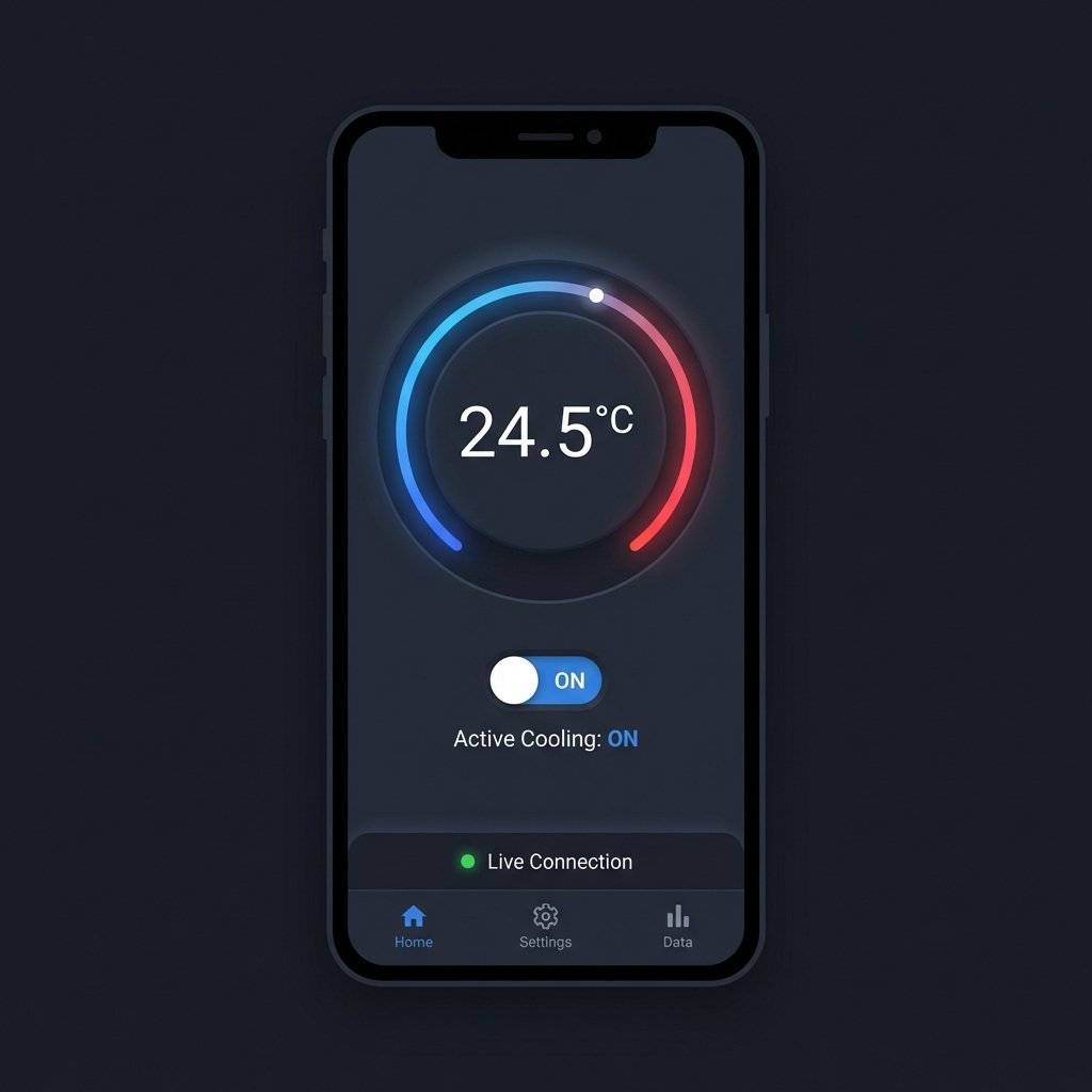
<div class="hub-card">
<h1>HUB STATUS</h1>
<div class="gauge" id="gaugeBody">
<div>
<span class="temp-display" id="temp">--</span>
<span class="unit">°C</span>
</div>
</div>
<div class="switch-container">
<span>Active Cooling</span>
<label class="switch">
<input type="checkbox" id="fanToggle" onchange="toggleFan()">
<span class="slider"></span>
</label>
</div>
<p style="margin-top:20px; color:#555; font-size:0.8rem;">
<span class="status-dot" id="connDot"></span> Live Connection
</p>
</div>
<script>
let failCount = 0;
function update() {
fetch('/status')
.then(res => res.json())
.then(data => {
document.getElementById('temp').innerHTML = data.t.toFixed(1);
document.getElementById('fanToggle').checked = data.r;
document.getElementById('connDot').classList.add('active');
failCount = 0;
let hue = 240 - (data.t - 15) * 10;
document.getElementById('gaugeBody').style.borderColor = 'hsl(' + hue + ', 100%, 50%)';
})
.catch(err => {
failCount++;
if(failCount > 2) document.getElementById('connDot').classList.remove('active');
});
}
function toggleFan() {
fetch('/toggle').then(() => update());
}
setInterval(update, 2000); // The Heartbeat
update();
</script>
</body>
</html>
)rawliteral";
void setup() {
Serial.begin(115200);
// 1. Hardware Init
pinMode(RELAY_PIN, OUTPUT);
digitalWrite(RELAY_PIN, HIGH); // Relay OFF (Active LOW usually)
// 2. Display Init
if(!display.begin(SSD1306_SWITCHCAPVCC, $0x3C$)) {
Serial.println(F("OLED Failed"));
for(;;);
}
display.clearDisplay();
display.setTextColor(WHITE);
display.println("Booting System...");
display.display();
// 3. WiFi Init
WiFi.mode(WIFI_STA);
WiFi.begin(ssid, password);
while (WiFi.status() != WL_CONNECTED) {
delay(500);
display.print(".");
display.display();
}
// 4. OTA Init
ArduinoOTA.setHostname("SafeHome-Hub-v1");
ArduinoOTA.setPassword(ota_pass);
ArduinoOTA.begin();
// 5. Server Routes
server.on("/", HTTP_GET, []() {
server.send_P(200, "text/html", index_html);
});
server.on("/status", HTTP_GET, []() {
// JSON API
String json = "{";
json += "\"t\":" + String(currentTemp) + ",";
json += "\"h\":" + String(currentHum) + ",";
json += "\"r\":" + String(relayState);
json += "}";
server.send(200, "application/json", json);
});
server.on("/toggle", HTTP_GET, []() {
relayState = !relayState;
digitalWrite(RELAY_PIN, relayState ? LOW : HIGH);
server.send(200, "text/plain", "OK");
});
server.begin();
dht.begin();
// Init average buffer
for(int i=0; i<FILTER_SIZE; i++) tempBuffer[i] = 25.0;
}
void loop() {
// CRITICAL: Handle Background Tasks
server.handleClient();
ArduinoOTA.handle();
unsigned long now = millis();
// TASK 1: Sensor Read (Every 2s)
if (now - lastSensorRead >= SENSOR_INTERVAL) {
lastSensorRead = now;
float newT = dht.readTemperature();
float newH = dht.readHumidity();
if (!isnan(newT)) {
// Moving Average
tempBuffer[bufferIndex] = newT;
bufferIndex = (bufferIndex + 1) % FILTER_SIZE;
float sum = 0;
for(int i=0; i<FILTER_SIZE; i++) sum += tempBuffer[i];
currentTemp = sum / FILTER_SIZE; // Use filtered value
currentHum = newH;
// Automation Logic (Thermostat)
if (currentTemp > 28.0 && !relayState) {
relayState = true;
digitalWrite(RELAY_PIN, LOW); // ON
} else if (currentTemp < 26.0 && relayState) {
relayState = false;
digitalWrite(RELAY_PIN, HIGH); // OFF
}
}
}
// TASK 2: UI Update (Every 1s)
// Decoupled from Sensor Read so animations feel smooth
if (now - lastDisplayUpdate >= DISPLAY_INTERVAL) {
lastDisplayUpdate = now;
display.clearDisplay();
display.setTextSize(1);
display.setCursor(0,0);
display.print("WikiHub IP:");
display.setCursor(0,10);
display.print(WiFi.localIP());
display.drawLine(0, 20, 128, 20, WHITE);
display.setTextSize(2);
display.setCursor(10, 30);
display.print(currentTemp, 1);
display.print(" C");
display.setTextSize(1);
display.setCursor(10, 55);
display.print(relayState ? "FAN: ON" : "FAN: OFF");
// Draw Activity Bar to show system is alive
int barWidth = (millis() % 1000) / 8; // 0 to 125
display.fillRect(0, 62, barWidth, 2, WHITE);
display.display();
}
}A generic “It doesn’t work” doesn’t help. We debug with data.
If your Serial Monitor spams garbage and resets:
Exception (29): vaddr=$0x3ff$....
This is a StoreProhibited error. You likely tried to write to a pointer that is NULL.
display.begin() before calling display.print()?readings array index out of bounds?You tried to read a 4-byte integer from an address not divisible by 4.
memcpy instead of casting pointers.Is your hub disconnecting?
Add this line to your updateOLED() function:
display.print(WiFi.RSSI());
-30 to -50 dBm: Perfect Signal.
-60 to -70 dBm: Good.
-80 dBm: Unstable packet loss.
-90 dBm: Disconnection imminent.
Solution: Add a capacitor across rails to boost radio stability.
If the OLED is dead, run this diagnostic code in setup():
Wire.begin();
for(byte i = 8; i < 120; i++) {
  Wire.beginTransmission(i);
  if (Wire.endTransmission() == 0) {
    Serial.print("Found I2C Device at: 0x");
    Serial.println(i, HEX);
  }
}
If this prints nothing? Your wires are broken.
The Hub is built. But a Systems Engineer is never finished. Because the code is modular, adding features is trivial:
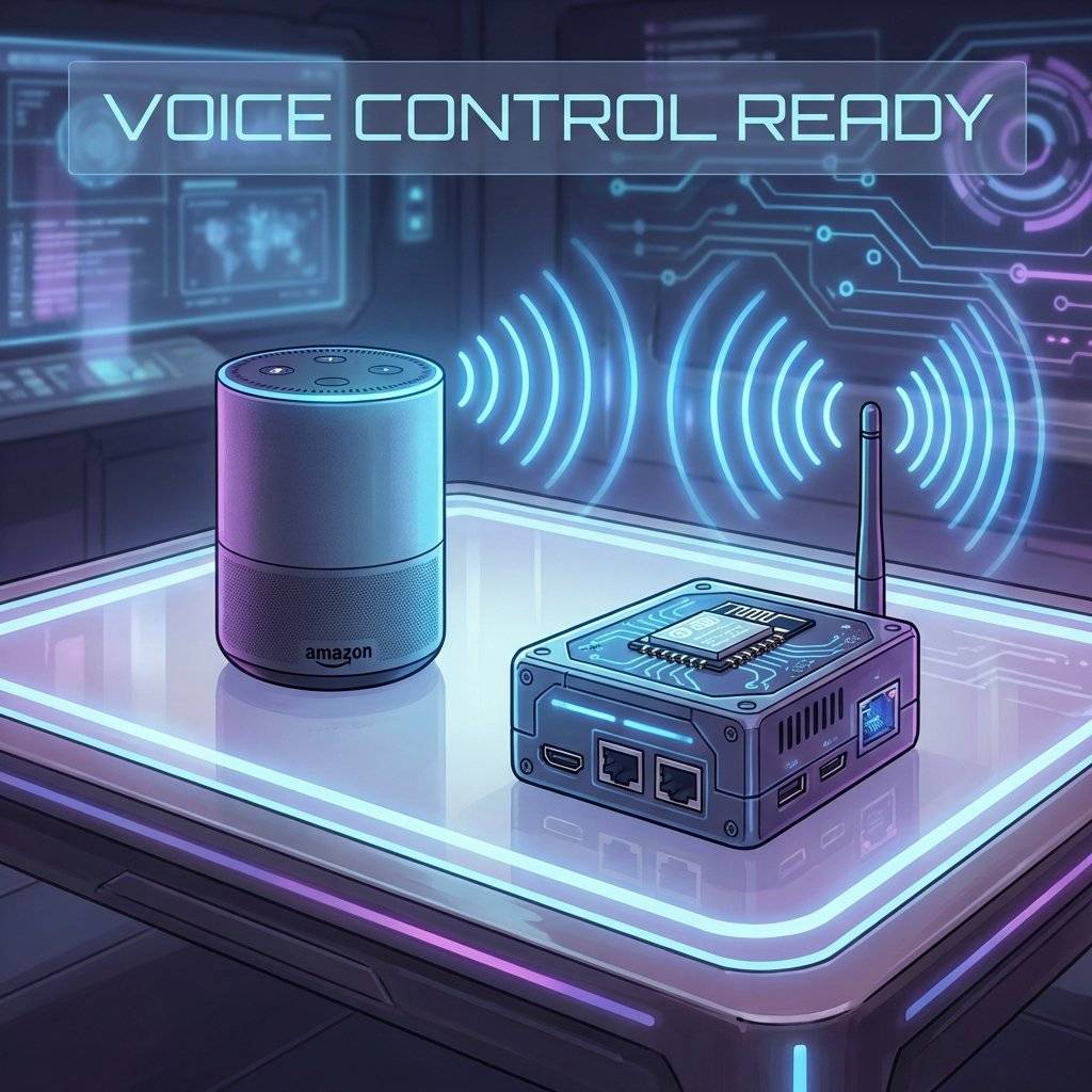
Voice Control: Integrate the SinricPro library to expose the Toggle function to Alexa/Google Home.
Data Logging: Send currentTemp to a Google Sheet via IFTTT webhook every hour.
Presence Detection: Add a PIR Motion Sensor (Day 29) to turn off the OLED when the room is empty to prevent burn-in.
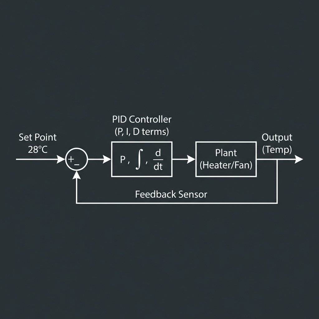
Currently, we use “Bang-Bang” control:
if (currentTemp > 28.0) relayState = true; // Fan ON
if (currentTemp < 28.0) relayState = false; // Fan OFF
This oscillates. Professional Solution: PID (Proportional-Integral-Derivative).
If you have followed us from Day 1 to Day 31: Congratulations. You have gone from blinking an LED to building a Cloud-Connected, Self-Updating, Multi-Tasking IoT Product. You have learned that “Smart Home” is not magic. It is just Physics, Code, and Logic.
The world is full of “Black Boxes” that you are not supposed to open. Open them. Build your own. Control your world.
This concludes the January Zero-to-Hero Series. See you in February for: PCB Design & Embedded Linux.
Q: Can I use an ESP32 instead? A: Yes, with minor pin definition changes.
Q: Can I power this with a battery? A: No, the relay and radio draw too much current for long-term battery use.
Q: Why is my temperature reading ? A: Heat from the CPU; ensure the sensor is mounted outside or has airflow.
Q: How do I access this from the internet? A: Use a VPN or MQTT broker; avoid port forwarding for security.
Copyright © 2026 TechnoChips. Open Source Hardware (OSHW).

A complete, end-to-end guide on building a secure, scalable IoT device using ESP32, MQTT, and AWS IoT Core. We bridge the gap between software logic and hardware reality.
Read More →
WiFi barely reaches your driveway. LoRa reaches the next town. Master the SX1278 module, Chirp Spread Spectrum physics, and build a 5km range sensor network.
Read More →
Stop polling your server every 5 seconds. Learn why Professional IoT uses MQTT. Master Pub/Sub architecture, QoS levels, Retained Messages, and Last Will & Testament.
Read More →