From Code to Reality: Building a Production-Grade IoT Device
A complete, end-to-end guide on building a secure, scalable IoT device using ESP32, MQTT, and AWS IoT Core. We bridge the gap between software logic and hardware reality.
Read More →
* SYSTEM.NOTICE: Affiliate links support continued laboratory research.
Today, we build bridges. We join the Internet of Things (IoT). We are switching to the ESP8266 (NodeMCU). It costs $3. It has built-in Wi-Fi. It is faster than the Uno. By the end of this guide, you will be controlling an LED from your smartphone via a website hosted on the chip itself.
The Arduino Uno uses the ATmega328P chip.
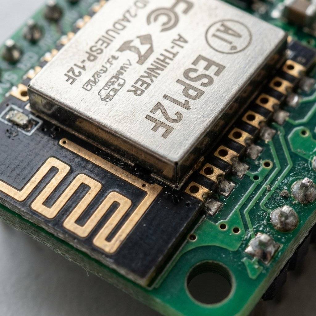
The NodeMCU uses the ESP8266 chip (specifically the ESP-12E/F module).
It is superior in almost every way, but it has one deadly catch.
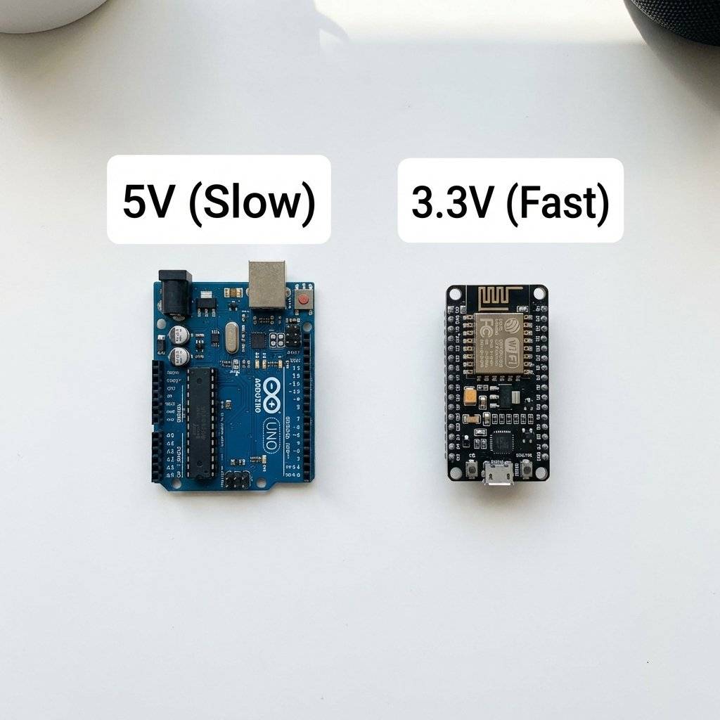
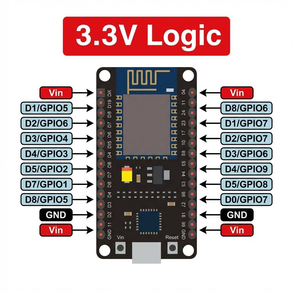
Your Arduino Uno operates at 5V. The ESP8266 operates at 3.3V. IF YOU CONNECT TO A GPIO PIN, YOU WILL KILL IT. You must treat this board with care.
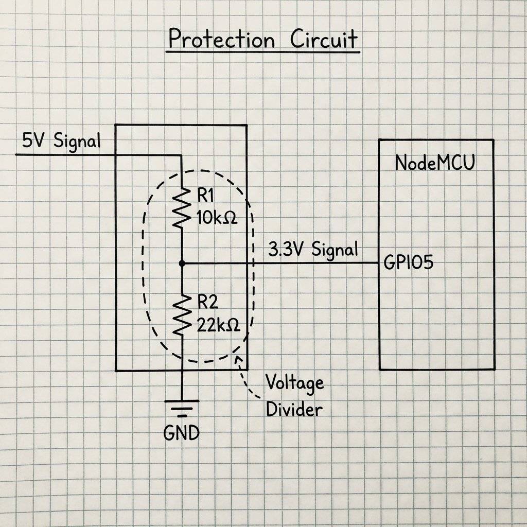
If you need to send a 5V signal (like from an Ultrasonic Sensor) to the ESP8266, you need a Voltage Divider. Two resistors: and .
This drops the 5V signal to a safe ~3.4V.
The Arduino IDE works, but it doesn’t know what an “ESP8266” is by default. You must install the Core.
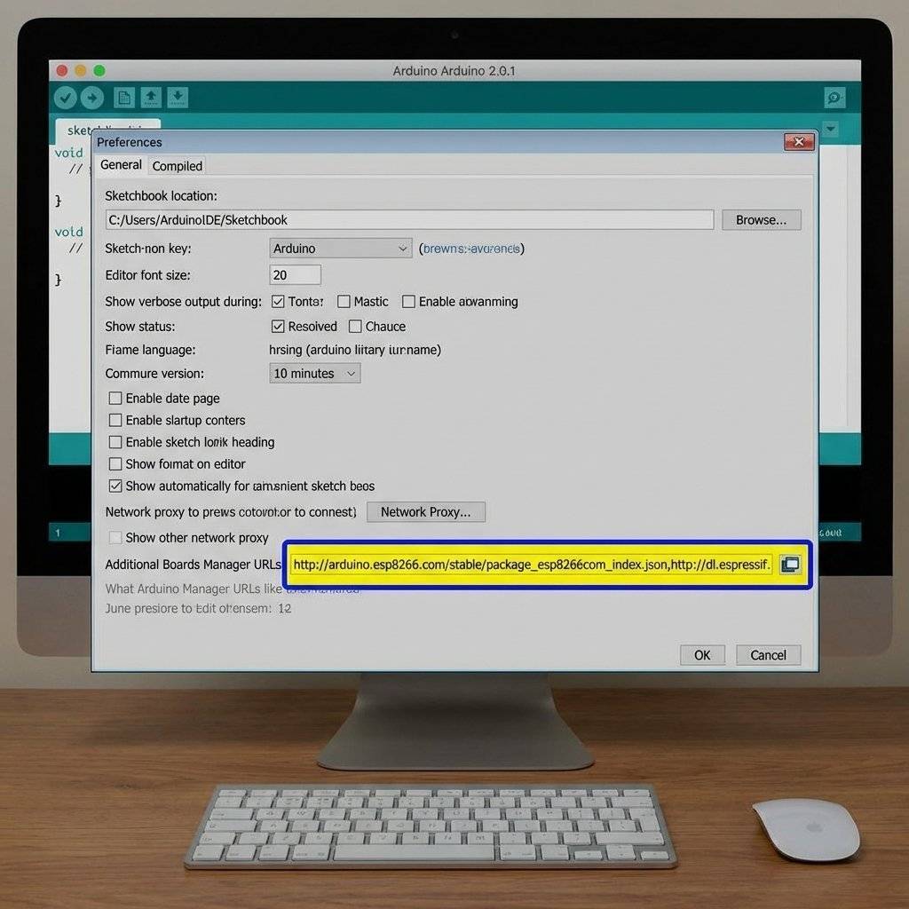
Let’s iterate. First, we just want to get on the network. Select your board: NodeMCU 1.0 (ESP-12E Module).
#include <ESP8266WiFi.h>
const char* ssid = "Your_WiFi_Name";
const char* password = "Your_WiFi_Password";
void setup() {
Serial.begin(115200); // Note the higher speed!
delay(10);
Serial.println();
Serial.print("Connecting to ");
Serial.println(ssid);
WiFi.begin(ssid, password);
while (WiFi.status() != WL_CONNECTED) {
delay(500);
Serial.print(".");
}
Serial.println("");
Serial.println("WiFi connected");
Serial.print("IP address: ");
Serial.println(WiFi.localIP());
}
void loop() {
// Nothing here yet
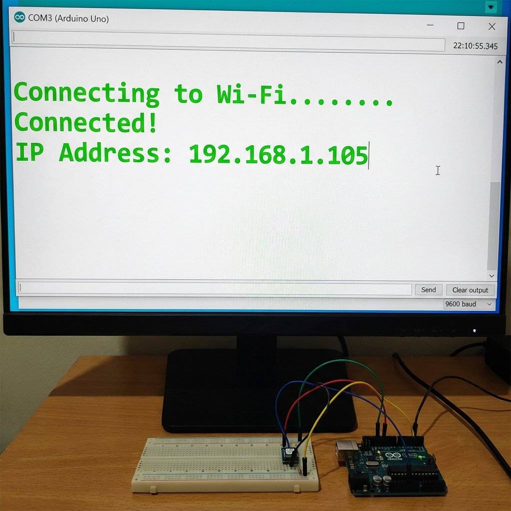
}If you see the output below, you are online.
One of the biggest advantages of the ESP8266 is Deep Sleep. If you are running on a battery, Wi-Fi kills it in hours (80mA draw). But you can put the chip into a coma where it draws 20uA (microamps). It basically turns itself off, except for a tiny timer. When the timer ends, it wakes up, connects to Wi-Fi, sends data, and sleeps again. This allows a single battery to last for years.
// Sleep for 10 seconds (Time in microseconds)
ESP.deepSleep(10e6);
Note: To wake up, you must connect the RST pin to D0 (GPIO16).
The ESP8266 has a split personality.
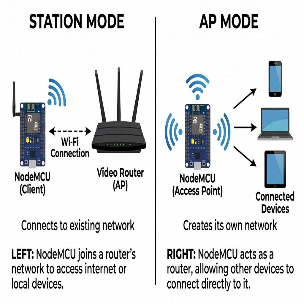
We will turn the ESP8266 into a website host. When you visit its IP address in Chrome, it will serve an HTML page with buttons. When you click a button, your browser sends a request back to the ESP8266 to turn on an LED.
GET /LED=ON.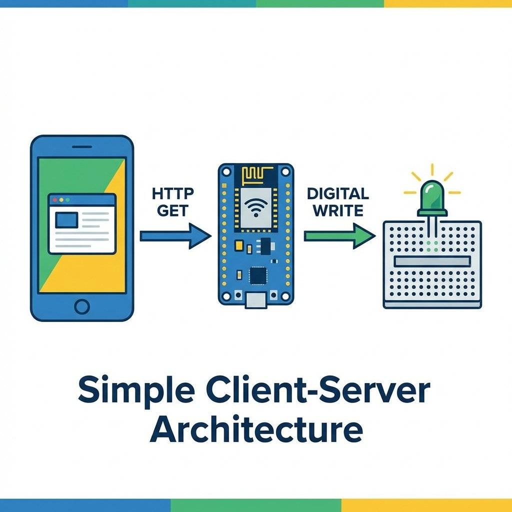
Imagine your ESP8266 is sealed inside a waterproof box on your roof. You want to change the code. Do you climb the ladder with a USB cable? No. You use OTA. This allows you to flash new code wirelessly over Wi-Fi from the Arduino IDE.
The Magic Code:
Add this to your setup():
// setup() ArduinoOTA.setHostname(“MyESP8266”); ArduinoOTA.setPassword(“admin123”);
ArduinoOTA.onStart( { String type = (ArduinoOTA.getCommand() == U_FLASH) ? “sketch” : “filesystem”; Serial.println(“Start updating ” + type); }); ArduinoOTA.onEnd( { Serial.println(“\nEnd”); }); ArduinoOTA.onProgress([](unsigned int progress, unsigned int total) { Serial.printf(“Progress: %u%%\r”, (progress / (total / 100))); }); ArduinoOTA.onError([](ota_error_t error) { Serial.printf(“Error[%u]: ”, error); if (error == OTA_AUTH_ERROR) Serial.println(“Auth Failed”); else if (error == OTA_BEGIN_ERROR) Serial.println(“Begin Failed”); else if (error == OTA_CONNECT_ERROR) Serial.println(“Connect Failed”); else if (error == OTA_RECEIVE_ERROR) Serial.println(“Receive Failed”); else if (error == OTA_END_ERROR) Serial.println(“End Failed”); }); ArduinoOTA.begin();
And add `ArduinoOTA.handle();` to your `loop()`.
Now, the “Port” in Arduino IDE will show up as a Network Port!

### The “Pro” Move: mDNS (Bonjour)

Typing `192.168.1.105` is annoying.
DHCP changes the IP every time you restart your router.
We want to type `http://livingroom.local`.
This is called **mDNS** (Multicast DNS).
```cpp
#include <ESP8266mDNS.h>

void setup() {
  // ... wifi connect ...
  if (MDNS.begin("livingroom")) {
    Serial.println("MDNS responder started");
  }
}
Now you can just type http://livingroom.local in your browser.
Note: Android phones still don’t natively support .local domains without an app, but iPhone and PC do.
Storing HTML in a String (like we do below) is messy.
Professional firmware stores files in the Flash Memory, just like a hard drive.
The ESP8266 has a file system called LittleFS.
You can upload an index.html file, a style.css file, and even script.js directly to the chip.
Then, your code simply says:
server.streamFile(LittleFS.open("/index.html", "r"), "text/html");
We will cover this in a future advanced guide, but know that it exists. Do not hardcode 5000 lines of HTML.
The previous HTML example was ugly.
Let’s use CSS to make it look like a modern App.
We will store the HTML in a raw String Literal R"rawliteral(...)rawliteral".
const char index_html[] PROGMEM = R"rawliteral(
<!DOCTYPE HTML><html>
<head>
  <meta name="viewport" content="width=device-width, initial-scale=1">
  <style>
    body { font-family: 'Arial', sans-serif; text-align: center; background-color: #2c3e50; color: white; }
    h1 { margin-top: 50px; }
    .switch { position: relative; display: inline-block; width: 60px; height: 34px; margin: 20px; }
    .switch input { opacity: 0; width: 0; height: 0; }
    .slider { position: absolute; cursor: pointer; top: 0; left: 0; right: 0; bottom: 0; background-color: #ccc; transition: .4s; border-radius: 34px; }
    .slider:before { position: absolute; content: ""; height: 26px; width: 26px; left: 4px; bottom: 4px; background-color: white; transition: .4s; border-radius: 50%; }
    input:checked + .slider { background-color: #2ecc71; }
    input:checked + .slider:before { transform: translateX(26px); }
    .card { background: #34495e; padding: 30px; border-radius: 10px; display: inline-block; box-shadow: 0 4px 8px rgba(0,0,0,0.2); }
  </style>
</head>
<body>
  <div class="card">
    <h1>Living Room Light</h1>
    <label class="switch">
<input type="checkbox" id="ledSwitch" onchange="toggleCheckbox(this)">
<span class="slider"></span>
    </label>
    <p id="status">OFF</p>
  </div>
  <script>
    function toggleCheckbox(element) {
      var xhr = new XMLHttpRequest();
      if(element.checked){ xhr.open("GET", "/led/on", true); document.getElementById("status").innerHTML = "ON"; }
      else { xhr.open("GET", "/led/off", true); document.getElementById("status").innerHTML = "OFF"; }
      xhr.send();
    }
  </script>
</body>
</html>
)rawliteral";
This single change makes your project feel like a commercial product.
(This uses the built-in ESP8266WebServer library).
#include <ESP8266WiFi.h>
#include <ESP8266WebServer.h>

const char* ssid = "Your_SSID";
const char* password = "Your_Password";

ESP8266WebServer server(80); // Port 80 is standard for HTTP

// The LED is on GPIO 5 (Pin D1 on NodeMCU)
int ledPin = 5;

void handleRoot() {
  String html = "<!DOCTYPE html><html>";
  html += "<head><meta name=\"viewport\" content=\"width=device-width, initial-scale=1\">";
  html += "<style>body{font-family: Helvetica; margin: 0px auto; text-align: center;}";
  html += ".button{background-color: #1abc9c; border: none; color: white; padding: 16px 40px;";
  html += "text-decoration: none; font-size: 30px; margin: 2px; cursor: pointer;}";
  html += ".button2{background-color: #e67e22;}</style></head>";
  html += "<body><h1>ESP8266 Web Control</h1>";
  html += "<p>LED State: " + String(digitalRead(ledPin) ? "ON" : "OFF") + "</p>";
  html += "<p><a href=\"/led/on\"><button class=\"button\">turn ON</button></a></p>";
  html += "<p><a href=\"/led/off\"><button class=\"button button2\">turn OFF</button></a></p>";
  html += "</body></html>";
  server.send(200, "text/html", html);
}

void handleLedOn() {
  digitalWrite(ledPin, HIGH);
  server.sendHeader("Location", "/"); // Redirect back to root
  server.send(303);
}

void handleLedOff() {
  digitalWrite(ledPin, LOW);
  server.sendHeader("Location", "/");
  server.send(303);
}

void setup() {
  Serial.begin(115200);
  pinMode(ledPin, OUTPUT);
  digitalWrite(ledPin, LOW);

  WiFi.begin(ssid, password);
  while (WiFi.status() != WL_CONNECTED) {
    delay(500);
    Serial.print(".");
  }
Serial.println("");
  Serial.print("IP: ");
  Serial.println(WiFi.localIP());

  // Define Routes
  server.on("/", handleRoot);
  server.on("/led/on", handleLedOn);
  server.on("/led/off", handleLedOff);

  server.begin();
  Serial.println("HTTP server started");
}

void loop() {
  server.handleClient(); // This checks for incoming connections
}You just put a $3 device on your home network. Is it safe?
Http vs Https: This example uses HTTP (Unencrypted). Anyone on your Wi-Fi can see the traffic.
Open Ports: Port 80 is open. If you “Port Forward” this on your router, the entire internet can toggle your LED. Do not do this without password protection.
Buffer Overflows: C++ allows memory manipulation. This is why we update libraries frequently.
The ESP8266 is more fragile than the Uno. If you see a “Stack Dump” in the serial monitor:
| Component | Quantity | Value | Notes |
|---|---|---|---|
| NodeMCU | 1 | ESP8266 | The dual-core IoT brain. |
| LED | 1 | Any | For visual feedback. |
| Resistor | 1 | For the LED. | |
| Resistor Pack | 1 | 10k/22k | For logic level shifting. |
| Micro-USB Cable | 1 | Data | For programming. |
| Breadboard | 1 | Any | For prototyping. |
You have severed the USB cable. You have a device that lives on the network. It serves a website. It controls hardware. This is the “Hello World” of IoT.
But a local web server is limited. You have to be home to use it. What if you want to turn on the heater before you get home? What if you want to log temperature data to a cloud database?
Next Up: On Day 30, we connect to the Cloud. We will use an API to fetch real-world data (Cryptocurrency prices, Weather forecasts) and display it on an OLED screen. We are building a Stock Ticker. See you tomorrow.

A complete, end-to-end guide on building a secure, scalable IoT device using ESP32, MQTT, and AWS IoT Core. We bridge the gap between software logic and hardware reality.
Read More →
WiFi barely reaches your driveway. LoRa reaches the next town. Master the SX1278 module, Chirp Spread Spectrum physics, and build a 5km range sensor network.
Read More →
Stop polling your server every 5 seconds. Learn why Professional IoT uses MQTT. Master Pub/Sub architecture, QoS levels, Retained Messages, and Last Will & Testament.
Read More →