From Code to Reality: Building a Production-Grade IoT Device
A complete, end-to-end guide on building a secure, scalable IoT device using ESP32, MQTT, and AWS IoT Core. We bridge the gap between software logic and hardware reality.
Read More →
* SYSTEM.NOTICE: Affiliate links support continued laboratory research.
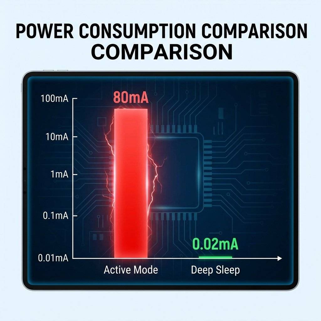
The biggest lie in IoT is “WiFi is power hungry”. Yes, if you keep the radio on, an ESP8266 consumes 80mA. A 2000mAh battery dies in 25 hours. But what if I told you that you could run that same ESP8266 on a coin cell for one year?
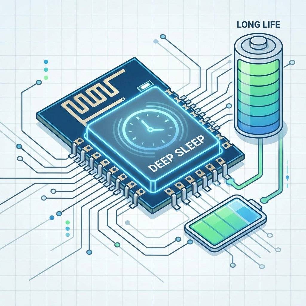
The secret is Deep Sleep. Most IoT devices spend 99.9% of their life doing nothing.
If you can make that “Sleep” consume 20uA instead of 80mA, you have unlocked the holy grail of remote sensing. Today, we master the art of doing nothing.
Let’s do the math. Energy is limited. Scenario: A standard 18650 Li-Ion Battery (2500mAh).
| Mode | Current | Life Expectancy |
|---|---|---|
| Active (WiFi ON) | 80 mA | ~31 Hours (1 Day) |
| Modem Sleep | 15 mA | ~6 Days |
| Light Sleep | 500 uA | ~6 Months |
| Deep Sleep | 20 uA | ~14 Years (Theoretical) |
Note: In reality, self-discharge and regulator inefficiency reduce the 14 years to ~2-3 years, but that is still infinitely better than 1 day.
When you call ESP.deepSleep(), the ESP8266 shuts down almost everything:
What stays (partially) ON?
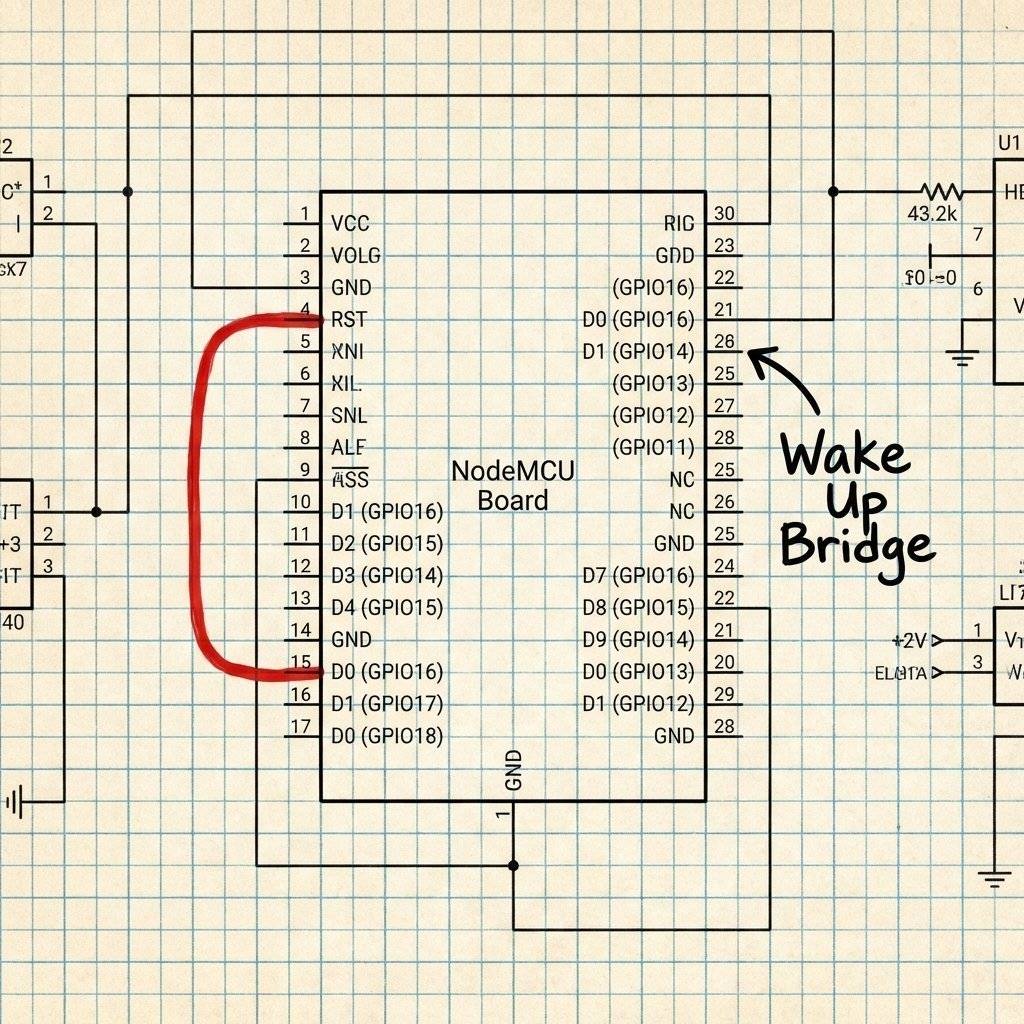
Here is the catch. The RTC Timer cannot wake up the CPU internally. When the timer finishes, it pulses GPIO16 (D0) LOW. To wake up the chip, the RST (Reset) pin must be pulled LOW.
The Solution: You MUST connect a wire between D0 and RST. Without this wire, the ESP8266 will sleep forever and never wake up. It enters a “Coma”.
Let’s blink an LED, then sleep for 5 seconds. Warning: Once you upload this, you might have trouble uploading again because the chip keeps turning off! (Hold the Flash button to recover).
void setup() {
Serial.begin(115200);
Serial.println("I am awake!");
pinMode(LED_BUILTIN, OUTPUT);
digitalWrite(LED_BUILTIN, LOW); // ON
delay(500);
digitalWrite(LED_BUILTIN, HIGH); // OFF
Serial.println("Going to sleep for 5 seconds...");
// Sleep for 5,000,000 microseconds
// WAKE_RF_DEFAULT: Turn WiFi on when we wake up
ESP.deepSleep(5e6, WAKE_RF_DEFAULT);
}
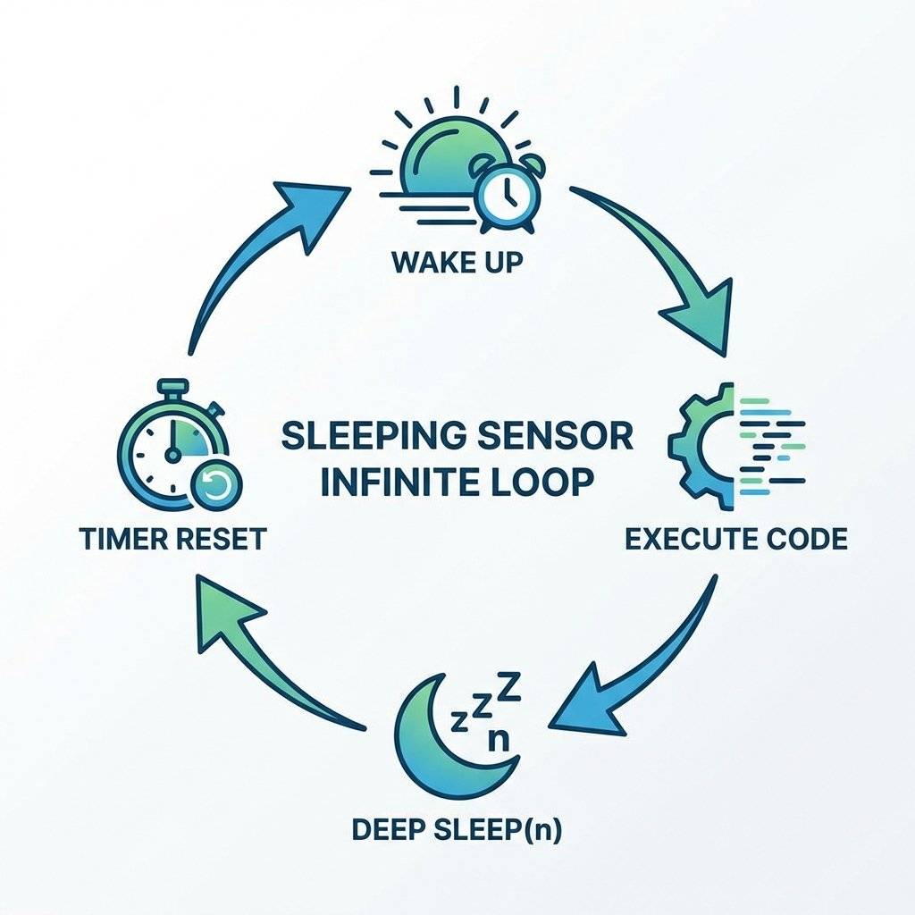
void loop() {
// We never reach here.
// After sleep, the code acts like a RESET.
// It starts from setup() again.
}
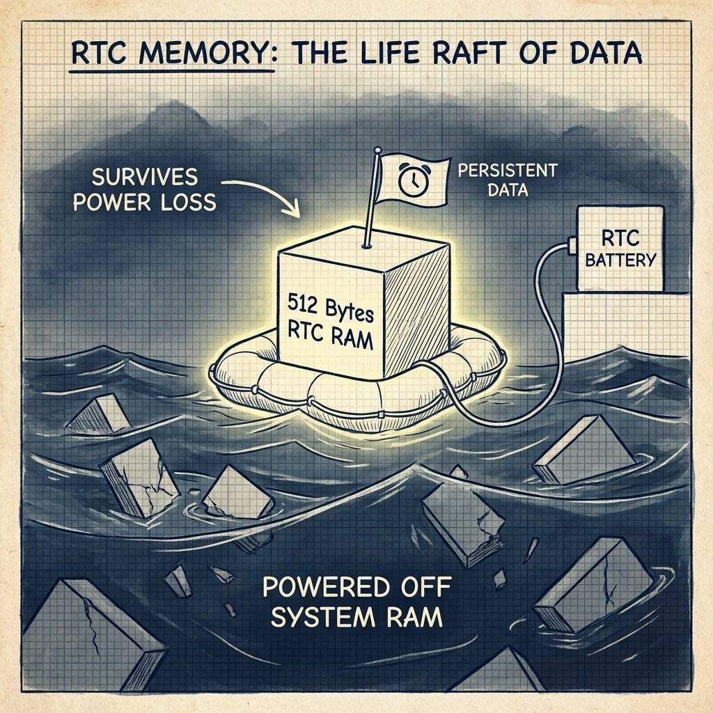
Since RAM is wiped during Deep Sleep, int counter = 0; resets to 0 every time you wake up.
If you want to count “How many times have I woken up?”, you need RTC Memory.
The ESP8266 has 512 bytes of battery-backed RAM.
We use the r_rtc_mem structure (or just raw byte access).
#include <ESP8266WiFi.h>

// Struct to hold our data
struct {
  uint32_t magic; // To check if data is valid
  int bootCount;
} rtcData;

void setup() {
  Serial.begin(115200);
// Read bucket 65 (User memory starts here)
  ESP.rtcUserMemoryRead(65, (uint32_t*) &rtcData, sizeof(rtcData));
// Check if first run (Magic Number check)
  if (rtcData.magic != 0xDEADBEEF) {
    rtcData.magic = 0xDEADBEEF;
    rtcData.bootCount = 0;
    Serial.println("First Boot / Power Cycle");
  } else {
    Serial.print("Boot Number: ");
    Serial.println(rtcData.bootCount);
  }
// Increment
  rtcData.bootCount++;
  // Save back to RTC
  ESP.rtcUserMemoryWrite(65, (uint32_t*) &rtcData, sizeof(rtcData));
  Serial.println("Sleeping...");
  ESP.deepSleep(10e6);
}

void loop() {}
Why Use RTC Memory vs EEPROM/SPIFFS?
If you follow this guide perfectly but use a standard “NodeMCU v2” or “Wemos D1 Mini” board, your battery will still die in a few weeks. Why? Because the board itself has components that eat power.
The Pro Solution:
Desolder the LED: Use a soldering iron to remove the power LED.
Bypass the LDO: If using a LiFePO4 battery (3.2V), connect it directly to the 3.3V pin, NOT the 5V/VIN pin. This skips the inefficient regulator entirely.
Use a Bare Module: Use an ESP-12F or ESP-07 module on a custom PCB (See Day 32). This gives you total control.
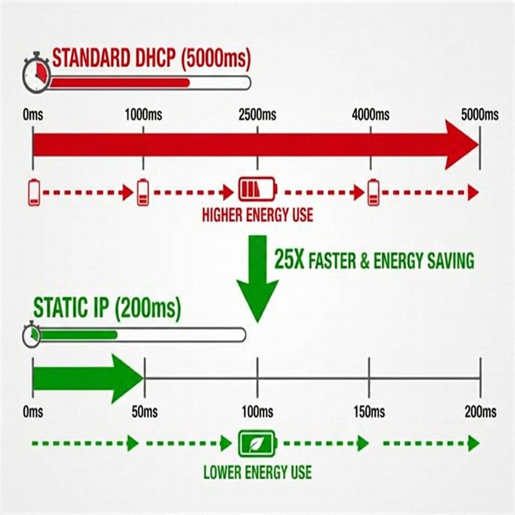
The biggest energy killer is establishing the WiFi connection.
The Strategy:
// Fast Connect Snippet
WiFi.config(ip, gateway, subnet);
WiFi.begin(ssid, password);
By skipping DHCP, you reduce “Active Time” from 5000ms to 500ms. That is a 10x battery life improvement.
You optimize your code to 20uA. But your battery dies in a week. Why? The Linear Regulator (LDO). On cheap NodeMCU boards, they use the AMS1117 regulator.
The AMS1117 consumes ~5mA quiescent current just to stay alive.
Even if the ESP consumes 0uA, the regulator drains 5mA.
The Fix: Use a “Low Quiescent Current” LDO.
Understanding the nuance is key.
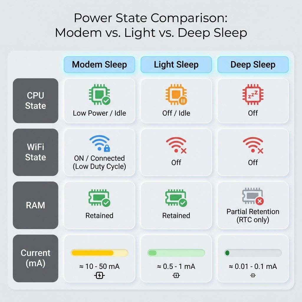
| Feature | Active | Modem Sleep | Light Sleep | Deep Sleep |
|---|---|---|---|---|
| CPU | ON | ON | Pending | OFF |
| WiFi | ON | OFF | OOFF | OFF |
| RAM | Retained | Retained | Retained | Lost |
| Current | 80 mA | 15 mA | 0.5 mA | 0.02 mA |
| Wakeup | N/A | Instant | Interrupt | Reset |
Normally, we wake up on a Timer (RST connected to D0).
But what if you want to wake up when a user presses a button?
Since Deep Sleep turns off CPU, attachInterrupt() does NOT work.
The Trick:
Connect the Button between RST and GND.
When pressed, it pulls RST low. When released, the chip resets (wakes up).
Note: You must handle the logic: “Did I wake up from Timer or Reset?”
Use ESP.getResetReason().
String reason = ESP.getResetReason();
// reason will be "Deep-Sleep Wake" or "External System"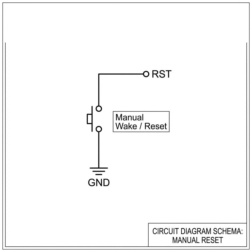
Let’s build a sensor that sends data to ThingSpeak every 10 minutes. BOM:
The Flow:
Total Active Time: 800ms. Sleep Time: 599.2 seconds. Avg Current . Battery Life .
Here is a secret that data sheets don’t tell you. When the ESP8266 wakes up and turns on WiFi, it pulls a massive 300mA - 400mA spike for about 50 microseconds. Small batteries (like CR2032 Coin Cells) have high Internal Resistance. When the ESP asks for 400mA, the battery voltage sags from 3V down to 1.8V. Result: The ESP Brownout Detector triggers, and the chip resets. It loops forever.
The Fix: A Bulk Capacitor. Place a large capacitor (1000uF or more) across VCC and GND close to the ESP.
Tip: Use Low-ESR capacitors (Tantalum or high-quality Electrolytic) for best results.
Deep Sleep is not just a function; it is a lifestyle. By respecting the energy budget, you move from “Toy” to “Tool”. Next time you deploy a sensor, ask yourself: Does this really need to be awake?
Copyright © 2026 TechnoChips. Open Source Hardware (OSHW).

A complete, end-to-end guide on building a secure, scalable IoT device using ESP32, MQTT, and AWS IoT Core. We bridge the gap between software logic and hardware reality.
Read More →
WiFi barely reaches your driveway. LoRa reaches the next town. Master the SX1278 module, Chirp Spread Spectrum physics, and build a 5km range sensor network.
Read More →
Stop polling your server every 5 seconds. Learn why Professional IoT uses MQTT. Master Pub/Sub architecture, QoS levels, Retained Messages, and Last Will & Testament.
Read More →