
The Invisible Instrument: Build a Light-Controlled Arduino Theremin
CONTENTS.log Table of Contents
Bill of Materials QTY: 6
* SYSTEM.NOTICE: Affiliate links support continued laboratory research.
Today, we stop building tools and start building Magic. We are going to build a musical instrument that you play without touching. You wave your hands in the air, and the pitch changes. It sounds like a 1950s UFO movie. It is called the Optical Theremin.
The Inspiration: Leon Theremin
In 1928, a Soviet physicist named Leon Theremin invented an instrument that used radio frequency oscillators. As his hand moved near an antenna, it disrupted the electromagnetic field, changing the pitch. It was spooky. It was revolutionary. It was the soundtrack to The Day the Earth Stood Still and Star Trek.
We cannot use radio waves today (too complex for a beginner circuit). Instead, we will use Light. We will replace the Antenna with an LDR (Light Dependent Resistor). We will replace the Speaker with a Piezo Buzzer. And the Arduino will be the conductor in the middle.
The Hardware Part 1: The LDR (The Eye)
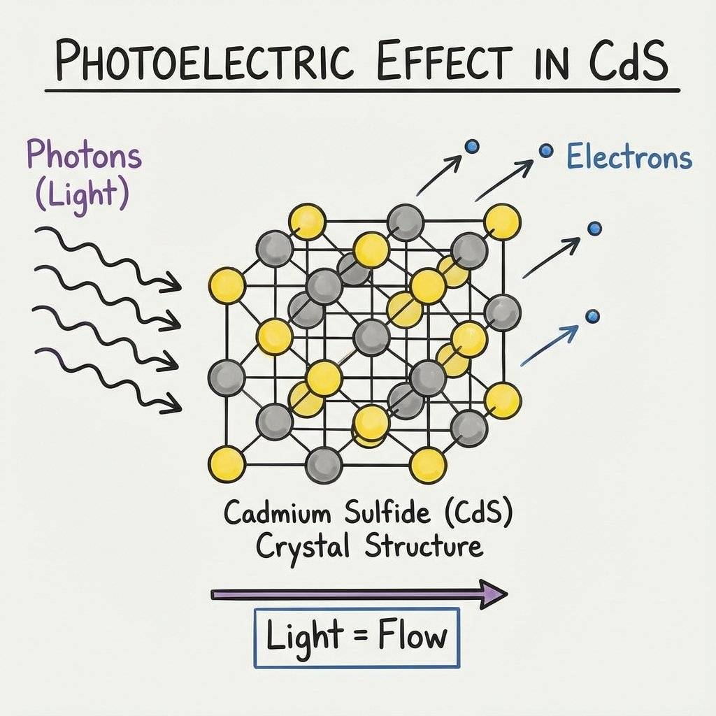
We mentioned the LDR briefly on Day 14. It is a small component with a squiggly orange face. LDR = Light Dependent Resistor. It is made of Cadmium Sulfide (CdS).
The Physics of Photons
How does it work?
- In darkness, the electrons inside the CdS are stuck. They cannot move.
- Resistance is High (Millions of ).
- When a Photon (light particle) hits the material, it knocks an electron loose.
- The electron is now free to flow.
- Resistance becomes Low (Hundreds of ).
It is literally powered by the impact of light particles. This is the same principle used in streetlights (to turn on at night) and your phone’s auto-brightness sensor.
The Wiring Trap
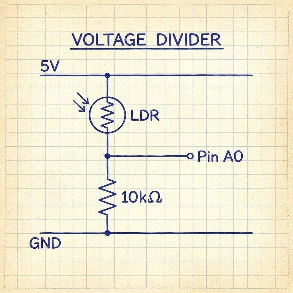
Since an LDR is a resistor, we cannot just plug it into a pin. Arduino pins measure Voltage, not Resistance. So, we must convert Resistance into Voltage. How? The Voltage Divider (Day 6 returns!).
We connect the LDR in series with a fixed resistor (usually ).
- As light changes -> LDR Resistance changes.
- As Resistance changes -> The ratio of the Voltage Divider changes.
- The voltage at the middle point moves up and down.
- We read that voltage with
analogRead(A0).
The Hardware Part 2: The Piezo (The Voice)
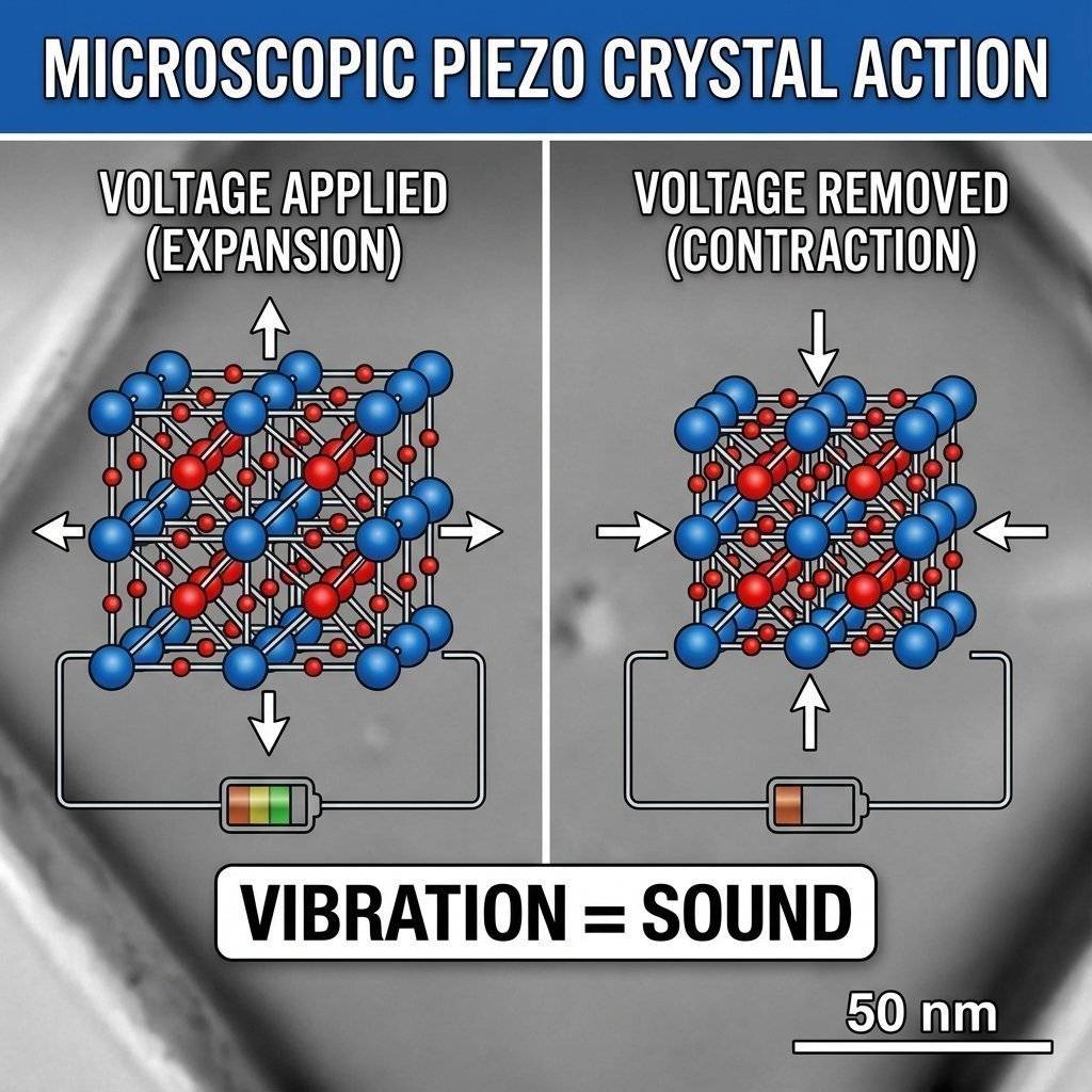
To make sound, we need vibration. A massive speaker uses a magnet and a coil to push air. But we are using a tiny black disc called a Piezo Buzzer.
The Piezoelectric Effect
Inside the plastic shell is a ceramic disc. This material has a crazy property: If you apply voltage to it, it physically expands. If you turn the voltage off, it shrinks. If you turn it on/off 440 times a second (), the disc vibrates 440 times a second. It slaps the air. That vibration hits your ear. You hear the note “A”.
Active vs Passive Buzzers
Warning: There are two types of buzzers.
- Active Buzzer: Has a sticker on top. If you give it 5V, it screams at a fixed tone. You cannot play music on it.
- Passive Buzzer: Exposed circuit board on bottom. If you give it 5V, it clicks once. To make sound, YOU have to pulse it manually. For this project, you need a PASSIVE Buzzer. (If you only have an Active one, this project will be very annoying, but it will technically work).
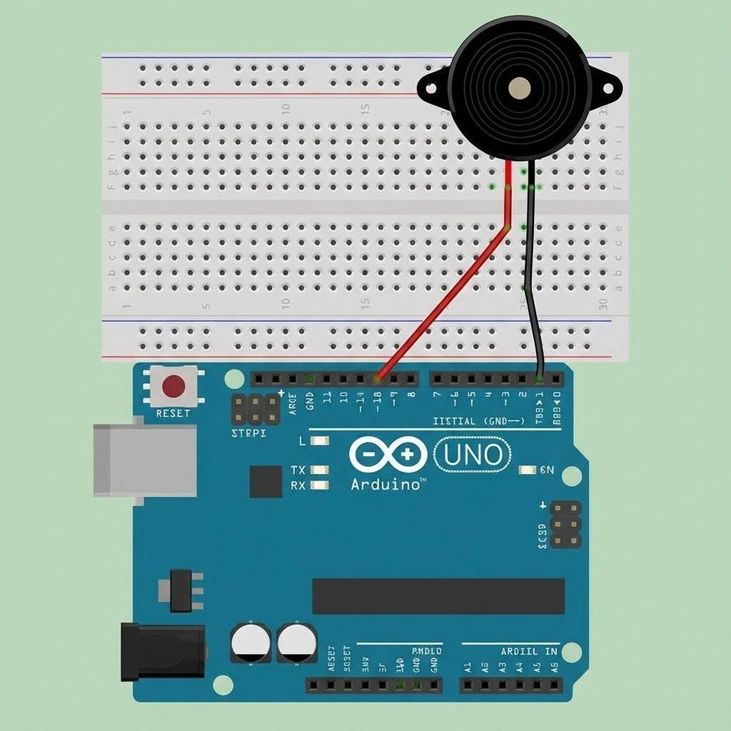
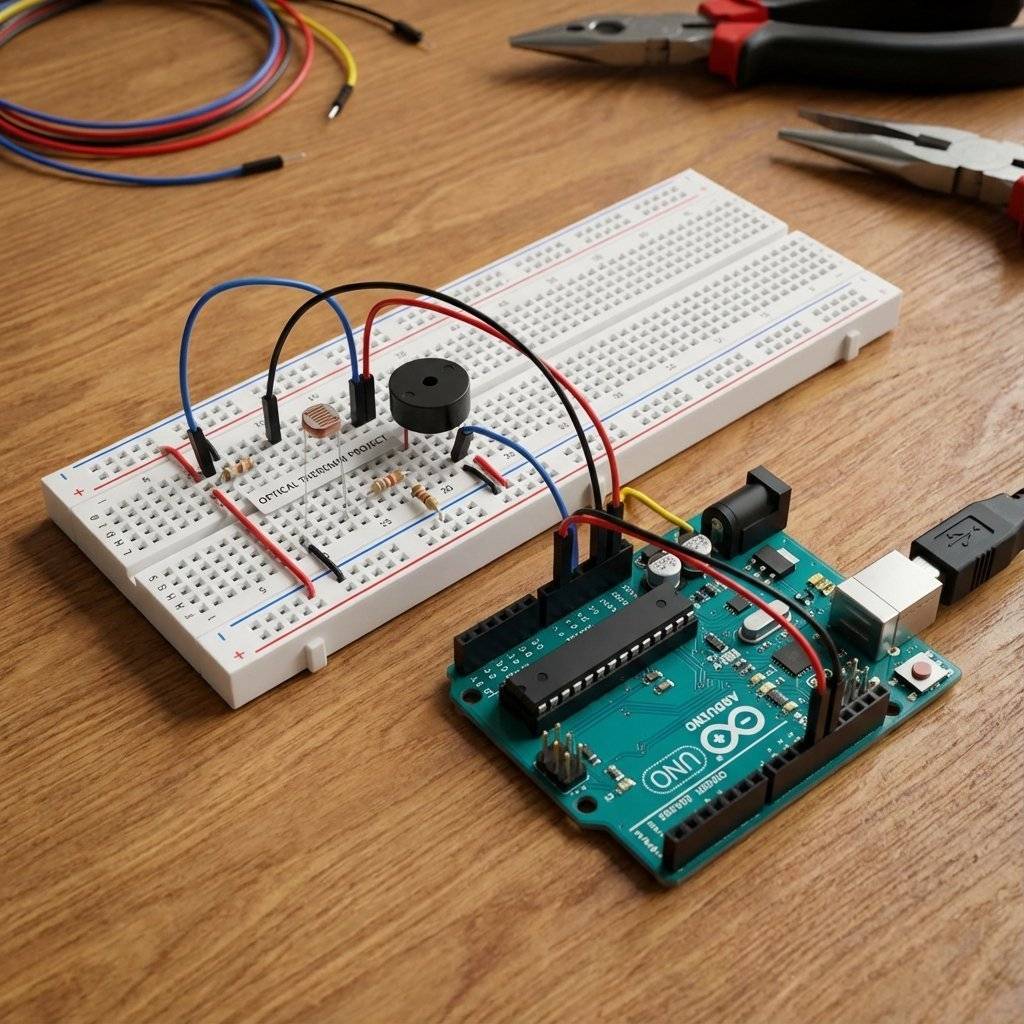
The Build
Let’s assemble the circuit. Components:
- Arduino Uno.
- LDR (Light Sensor).
- Resistor (Brown-Black-Orange).
- Piezo Buzzer (Passive).
- Wires.
Wiring Instructions:
- LDR Leg 1: To 5V.
- LDR Leg 2: To A0.
- resistor: From A0 to GND. (This creates the voltage divider at A0).
- Buzzer Positive (+): To Pin 8.
- Buzzer Negative (-): To GND.
The Code Phase 1: Testing the Sensor
Before we make noise, let’s verify the eye works. We need to know the range of our LDR. Every room is different.
- Dark room might read 800.
- Bright room might read 100.
- Flashlight might read 10.
Upload this “Calibration Sketch”:
void setup() {
  Serial.begin(9600);
}

void loop() {
  int lightLevel = analogRead(A0);
  Serial.print("Light: ");
  Serial.println(lightLevel);
  delay(100);
}
The Calibration Protocol:
-
Open Serial Monitor.
-
Wave your hand over the sensor.
-
Write down the Lowest Number (Shadow). Let’s say 200.
-
Write down the Highest Number (Ambient Light). Let’s say 800. These are your “Min” and “Max” values. We need them for the math step.
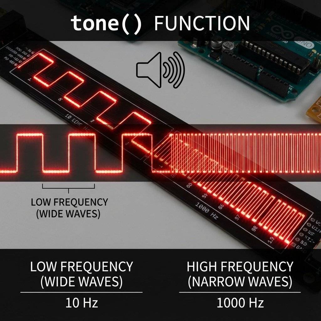
The Code Phase 2: The tone() Function
Arduino has a built-in library for music.
tone(pin, frequency, duration)
- Pin: Where the buzzer is (8).
- Frequency: The pitch in (e.g., is Middle C).
- Duration: How long to play (optional).
If we run tone(8, 440), it generates a square wave at on Pin 8 continuously.
To stop it, we use noTone(8).
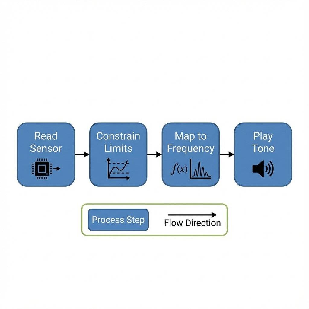
The Code Phase 3: The Theremin Logic
We need to map the light () to sound ( - ).
Remember the map() function from Day 14?
This is its time to shine.
void loop() {
  int sensorValue = analogRead(A0); // Read Light (e.g., 600)
  // Convert 200-800 input to 100-1000Hz output
  // CHANGE 200 AND 800 TO YOUR CALIBRATION NUMBERS!
  int pitch = map(sensorValue, 200, 800, 100, 1000);
  tone(8, pitch);
  delay(10); // Stability
}
Upload it. Now, move your hand. As your shadow falls on the sensor, the pitch should drop. As you pull away, the pitch rises. You are playing the light.

Troubleshooting The Glitches
You might notice some issues.
- The Screeching: Even when you cover it completely, it still shrieks.
Fix: Add a “Silence Threshold”.
if (sensorValue < 100) { noTone(8); } else { tone(8, pitch); }
- The Jitter: The sound sounds wobbly or “scratchy”.
Fix: The LDR reading is fluctuating. Use the Averaging technique we learned on Day 14.
- Too Quiet: The buzzer is weak.
Fix: Remove the sticker! Most buzzers come with a “Remove after washing” seal. Peel it off.
Advanced Logic: Constraint
What happens if the light gets BRIGHTER than 800?
Or DARKER than 200?
The map() function doesn’t stop at the limits. It extrapolates.
It might give you a negative frequency, or a frequency of .
Both will confuse the tone() function.
We need a bodyguard.
We need constrain().
val = constrain(val, min, max);
The Final Professional Code:
const int ldrPin = A0;
const int piezoPin = 8;
const int ldrMin = 200; // From Calibration
const int ldrMax = 800; // From Calibration

void setup() {
  // No setup needed for Analog Input
}

void loop() {
  int reading = analogRead(ldrPin);
  // 1. Clamp the reading to safe limits
  reading = constrain(reading, ldrMin, ldrMax);
  // 2. Map to Audio Frequencies (Pentatonic Scale range roughly)
  int pitch = map(reading, ldrMin, ldrMax, 100, 2000);
  // 3. Play
  tone(piezoPin, pitch);
  delay(10);
}
Deep Dive: The Smoothing Algorithm (Running Average)
You might notice the sound is “jittery”.
This is because analogRead() is noisy. One millisecond it reads 500, the next 502, the next 499. This makes the pitch wobble. To fix this, we use a Running Average. Instead of believing every single reading, we average the last 10 readings.
const int numReadings = 10;
int readings[numReadings];  // The readings from the analog input
int readIndex = 0;          // The index of the current reading
int total = 0;              // The running total
int average = 0;            // The average

void setup() {
  for (int i = 0; i < numReadings; i++) {
    readings[i] = 0;
  }
}

void loop() {
  // Subtract the last reading:
  total = total - readings[readIndex];
  // Read from the sensor:
  readings[readIndex] = analogRead(A0);
  // Add the reading to the total:
  total = total + readings[readIndex];
  // Advance to the next position in the array:
  readIndex = readIndex + 1;

  // If we're at the end of the array...
  if (readIndex >= numReadings) {
    // ...wrap around to the beginning:
    readIndex = 0;
  }

  // Calculate the average:
  average = total / numReadings;
  // Use 'average' instead of 'analogRead(A0)' for the pitch!
  int pitch = map(average, 200, 800, 100, 1000);
  tone(8, pitch);
  delay(1);
}
This makes the instrument feel “heavy” and smooth, like a real cello string.
Pro Tip: Playing Real Notes (Arrays)
Right now, our Theremin slides through every frequency (100, 101, 102…). This sounds like a siren. If you want it to play Music, you need to snap the values to specific Notes (C, D, E, F, G). We can use an Array (Day 13!) to hold note frequencies.
int notes[] = {262, 294, 330, 349, 392, 440, 494, 523}; // C Major Scale
//             0    1    2    3    4    5    6    7

void loop() {
  int sensorValue = analogRead(A0);
  // Map sensor (200-800) to Array Index (0-7)
  int noteIndex = map(sensorValue, 200, 800, 0, 7);
  // Safety Constraint
  noteIndex = constrain(noteIndex, 0, 7);
  tone(8, notes[noteIndex]);
  delay(10);
}
Now, as you move your hand, it plays a melody instead of a slide. You have effectively built a Laser Harp Logic.
Science Class: Why square waves sound “Gamey”
If you listen to a real violin, the sound wave is complex and jagged. If you listen to a flute, it is a smooth sine wave. The Arduino produces a Square Wave. It is brutal. ON. OFF. ON. OFF. There is no curve. This gives it that distinct “8-bit Nintendo” sound. To make it sound like a piano, you would need a DAC (Digital to Analog Converter) and wave tables, which goes beyond the Arduino Uno’s basic capabilities. For now, embrace the retro aesthetic.
Challenge: The “Reverse” Theremin
Right now:
- Dark (Shadow) = Low Pitch.
- Light = High Pitch.
Can you invert it?
Make the shadow create high-pitched screams?
Hint: Swap the last two numbers in the map function.
map(val, min, max, 2000, 100);
Challenge: The Laser Harp
If you have a Laser Pointer… And you have 3 LDRs… Can you set them up so the lasers hit the LDRs? And when you “break” the beam with your finger, it plays a specific note? This is the Laser Harp, a favorite project of Jean-Michel Jarre. It is just 3 copies of this circuit running in parallel!
The Bill of Materials (BOM)
| Component | Quantity | Value | Notes |
|---|---|---|---|
| Arduino Uno | 1 | Any | The Brain of the operation. R3 or R4 both work perfectly. |
| LDR | 1 | 5mm CdS | Light Dependent Resistor. Values vary by brand (GL5516 is common). |
| Resistor | 1 | Brown-Black-Orange. Essential for the voltage divider. | |
| Piezo Buzzer | 1 | Passive | Must be Passive! Active buzzers will just scream at one tone. |
| Wires | 6+ | M-M | You need enough length to position the sensor comfortably. |
| Breadboard | 1 | Half+ | Standard prototyping area. |
Conclusion
You have built a device that translates the invisible (photons) into the audible (sound waves). This is the essence of engineering. We shape the world around us.
You have now mastered:
- Input: Reading sensors.
- Processing: Mapping and Logic.
- Output: Generating frequencies.
Tomorrow, on Day 17, we finally give our robot legs. We are moving from “Light and Sound” to Action. We are going to learn about DC Motors, Transistors, and high-current circuits. We are going to make things move.
See you on Day 17.