Build a Working Radar: Mapping Rooms with Arduino, Ultrasonics, and Servos
Combine sensors and servos to build a real-time scanning radar. Learn Polar Coordinates, Serial Plotting, and data visualization.
Read More →
* SYSTEM.NOTICE: Affiliate links support continued laboratory research.
Today, we want to move physical matter. We want to spin a fan, drive a wheel, or lift a robot arm. We need Torque. We need Power. We need the DC Motor.
But there is a problem. A big, smoking problem. If you plug a motor directly into your Arduino, you will kill your Arduino. Instantly. Ideally with a dramatic “Pop” sound and the smell of burning silicon.
Today, we learn how to tame the beast using the Transistor.

To understand the danger, we need to talk about Current (Amps). The Arduino’s processor (ATmega328P) is a brain, not a muscle.
Do the math. The motor tries to suck through a pin designed for . It is like trying to suck a watermelon through a straw. The straw bursts. The chip melts. The magic smoke comes out.
Rule #1 of Robotics: NEVER connect a motor directly to an Arduino Pin.

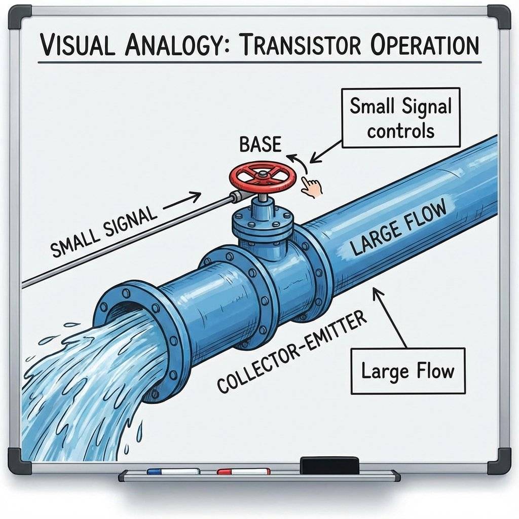
We need a middleman. We need a device that takes a tiny signal from the Arduino (Connect/Disconnect) and uses it to control a massive flow of power from a battery to the motor. This device is the Transistor.
Think of it like a Water Valve.
You (the Arduino) only have to touch the handle. You don’t have to hold back the water yourself.
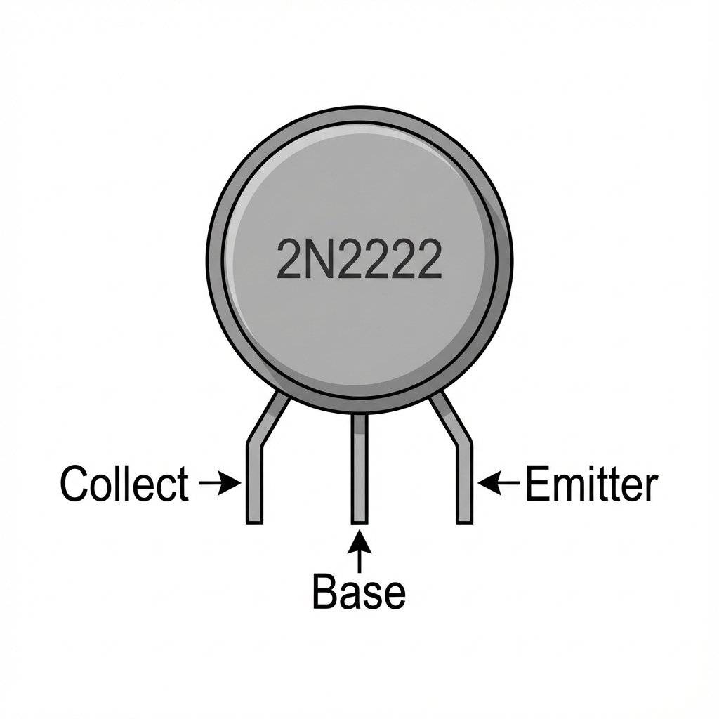
For small motors, we use a BJT (Bipolar Junction Transistor). The most common one is the 2N2222 (or PN2222). It is a small black cylinder with 3 legs.
If you hold it with the Flat Face facing you, the legs are (from Left to Right):
Mnemonic: “Current Flows in C, Out E”.
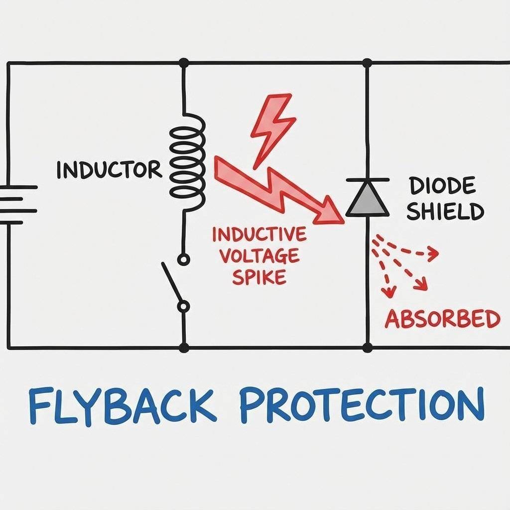
Motors are nasty. They are Inductive Loads. Inside a motor, there are coils of wire and magnets. When you run electricity through a coil, it creates a magnetic field. When you turn the power OFF, that magnetic field collapses. Physics says this collapsing field must generate electricity. It shoots a massive Voltage Spike (up to !) backwards through the wires. This “Kickback” (or Flyback) can shock your Arduino and reset it, or destroy the transistor.
The Fix: A Flyback Diode (1N4007 or 1N4148). A diode is a one-way valve for electricity. We place it across the motor in Reverse Bias.
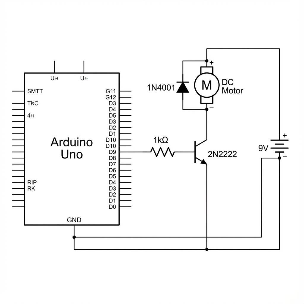
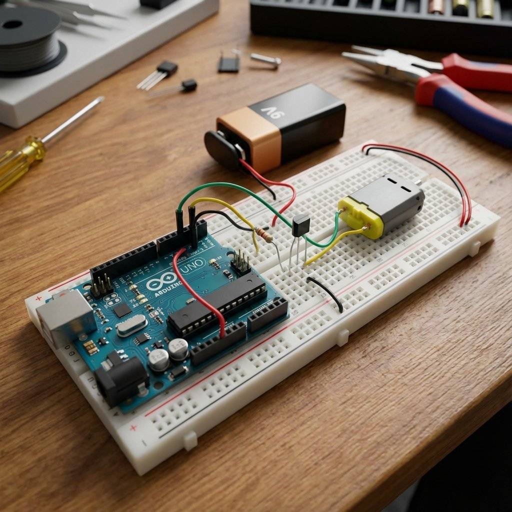
Let’s build the standard “Low Side Switch” circuit. Components:
Wiring Instructions:
Since the transistor is just a switch, we can use digitalWrite.
const int motorPin = 9;

void setup() {
  pinMode(motorPin, OUTPUT);
  Serial.begin(9600);
}

void loop() {
  Serial.println("Motor ON");
  digitalWrite(motorPin, HIGH); // Turn Transistor ON -> Motor Runs
  delay(1000);
  Serial.println("Motor OFF");
  digitalWrite(motorPin, LOW); // Turn Transistor OFF -> Motor Stops
  delay(1000);
}
Observation: When Pin 9 goes HIGH, the Transistor Base gets . It opens the floodgates. The from the battery rushes through the motor to Ground. The motor spins.
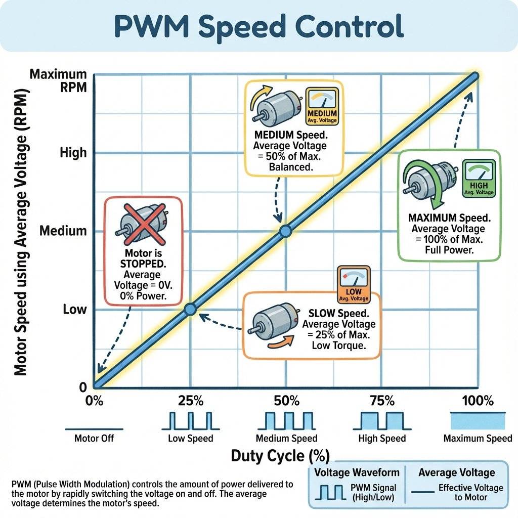
Because we used Pin 9 (a PWM pin), we can control the speed! Just like fading an LED. We are pulsing the motor power. The motor’s inertia smooths out the pulses, so it just spins slower.
void loop() {
  // Accelerate
  for (int speed = 0; speed <= 255; speed++) {
    analogWrite(motorPin, speed);
    delay(10);
  }
  // Decelerate
  for (int speed = 255; speed >= 0; speed--) {
    analogWrite(motorPin, speed);
    delay(10);
  }
}
Torque Warning: At very low PWM values (e.g., 20 or 30), the motor might hum but not move. It needs a minimum amount of power to overcome static friction. Usually, motors start spinning around PWM 50-60.
This is the #1 mistake beginners make. You have a battery for the motor. You have a USB cable for the Arduino. You MUST connect the Battery Negative to the Arduino GND. Voltage is relative. If you don’t connect the grounds, the Arduino’s “” signal has no reference point for the transistor to understand. Nothing will work. Rule: Always tie the grounds together (but NEVER the Positives!).
We used a BJT (2N2222) today. It is cheap and good for small motors (). But it runs hot. It wastes power. For bigger motors (Drills, Drones, RC Cars), we use MOSFETs (Metal Oxide Semiconductor Field Effect Transistor). MOSFETs are voltage-controlled (Gate). BJTs are current-controlled (Base). MOSFETs are much more efficient for high power. We will use an IRLZ44N Logic Level MOSFET in future high-power projects. For now, the 2N2222 is your friend.
You might hear engineers talk about “Biasing” a transistor. For motors, we don’t care about linear amplification (like in an audio amplifier). We want the transistor to be fully ON or fully OFF. This “Fully ON” state is called Saturation.
Why does this matter? If you don’t use enough Base Current (e.g. you use a resistor instead of ), the transistor won’t fully open. It will act like a bottleneck. Your motor will run slow, and the transistor will burn up. Everything we do today relies on achieving Saturation.
What if your motor is huge? Like a treadmill motor? What if it generates so much electrical noise that it crashes your Arduino even with a diode? You need Total Isolation. You need an Optocoupler (like the 4N35).
An Optocoupler is a chip with an LED inside and a light-sensitive transistor inside.
The 2N2222 has a gain (hFE) of about 100. If you put into the Base, you get at the Collector. What if you need ? You would need at the Base, which might kill the Arduino pin. The solution is a Darlington Pair (like the TIP120). It is two transistors inside one package, chained together. Gain 1 * Gain 2 = Total Gain. 100 * 100 = 10,000. You can drive a massive motor with a whisper of current. Note: They have a higher voltage drop (1.4V), so they get hotter than single transistors. Why did we put a resistor between the Arduino and the Transistor Base? Because the Base-Emitter junction inside the transistor looks like a short circuit (technically a diode) to the Arduino. Without the resistor, the Arduino would dump unlimited current into the Base, protecting the Transistor but killing the Arduino pin. The limits current to a safe .
You have an LDR (from Day 16). You have a Motor (Fan). Combine them! Build a system that turns the Fan ON when it gets bright (simulating a hot sunny day). Or, if you have a temperature sensor (Thermistor), use that.
int light = analogRead(A0);
if (light > 600) {
  analogWrite(9, 255); // Full blast
} else if (light > 400) {
  analogWrite(9, 128); // Half speed
} else {
  digitalWrite(9, LOW); // Off
}
If your motor is dead, don’t panic. Follow this order:
The “Click” Test:
Do you hear a faint “whine” or “click” when power is applied?
softStart minimum.The Common Ground Check:
Put your Multimeter logic on Continuity Mode (Beep).
The Transistor Orientation:
Look at the 2N2222. Is the Flat Side facing you?
The Base Resistor Check:
Did you accidently use or instead of ?
The Diode Direction:
If the diode is backwards (Stripe to Negative), you have created a Short Circuit.
The “Magic Smoke” Check:
Does the Arduino still run the “Blink” sketch?
| Component | Quantity | Value | Notes |
|---|---|---|---|
| Arduino Uno | 1 | Any | The Brain of the operation. |
| DC Motor | 1 | Small Hobby Motor (“130 Size”). | |
| Transistor | 1 | 2N2222 | NPN Bipolar Junction Transistor. |
| Diode | 1 | 1N4007 | Rectifier Diode. |
| Resistor | 1 | Base current limiter (Brown-Black-Red). | |
| Battery | 1 | Power for the Motor. | |
| Battery Clip | 1 | To connect to breadboard. | |
| Wires | 10+ | M-M | Breadboard jumper wires. |
| Breadboard | 1 | Half+ | Standard prototyping area. |
DC Motors are “noisy”. As the brushes spin inside, they spark. This creates Radio Frequency (RF) interference. It can confuse your sensors or reset the Arduino. The Fix: Solder a small 0.1uF Ceramic Capacitor across the motor terminals. It acts like a shock absorber for the electrical noise, shorting the high-frequency sparks before they travel down the wires. If your robot builds are “glitchy”, this is usually the missing piece.
You might have noticed something. Our Transistor circuit allows us to turn the motor ON and OFF. It allows us to control SPEED (PWM). But it does NOT allow us to Reverse Direction. Why? Because the current always flows from Collector to Emitter. One way. To reverse a DC motor, you must swap the Positive and Negative wires.
To do this electronically, we need Four Transistors arranged in an “H” shape. This is called an H-Bridge.
Building an H-Bridge from scratch is complex (and prone to “Shoot-Through” short circuits). In the future, we will use dedicated H-Bridge Chips like the L293D or L298N. For today, master one direction first!
When a motor starts from 0 RPM, it is “Stalled” for a split second. It draws maximum current (Inrush Current). This spike can dim your lights or reset your Arduino. To prevent this, never jump from 0 to 255 instantly. Use a “Soft Start” wrapper function:
void softStart(int targetSpeed) {
  for (int i = 0; i <= targetSpeed; i += 5) {
    analogWrite(9, i);
    delay(10); // Ramp up over ~500ms
  }
}
Use this whenever you turn the motor ON. Your power supply will thank you.
Before you use ANY distinct scavenged motor with a 2N2222, check its Stall Current.
You have successfully broken the 40mA barrier. You are now controlling High Power with Low Power. This is the fundamental concept behind every machine in the world. From the tiny vibrator in your phone to the massive motors in a Tesla Model S to the hydraulics of a Space Shuttle… It is all just small signals controlling big valves.
Tomorrow, on Day 18, we go even bigger. We will control Alternating Current (AC). We will learn about the Relay. We will learn how to turn on a real lightbulb or a coffee machine safely. (Don’t actually plug in current yet, we will stay safe with , but the theory is the same!).
See you on Day 18.

Combine sensors and servos to build a real-time scanning radar. Learn Polar Coordinates, Serial Plotting, and data visualization.
Read More →
Turn your Arduino into a robotics controller. Master the SG90 Servo Motor, understand closed-loop control systems, and build precise robotic joints.
Read More →
Give your robot eyes. Learn how the HC-SR04 Ultrasonic Sensor works, master the physics of sound, and build a precision Parking Sensor using Arduino.
Read More →