Build a Working Radar: Mapping Rooms with Arduino, Ultrasonics, and Servos
Combine sensors and servos to build a real-time scanning radar. Learn Polar Coordinates, Serial Plotting, and data visualization.
Read More →
* SYSTEM.NOTICE: Affiliate links support continued laboratory research.
Today, we go old school. We are going to use a component that was invented in 1835. It makes a satisfying “Click-Clack” sound. It can control loads safely. It is the Electromechanical Relay.
Safety Warning: Today’s theory involves High Voltage concepts. DO NOT cut open your desk lamp cord and wire it up unless you are a certified electrician or have adult supervision. We will learn the Theory and simulate the High Voltage part with LEDs. Electricity is invisible and it hurts. Respect it.

A relay is simply A Switch operated by an Electromagnet. Inside the blue plastic box, there is no silicon magic. It is purely mechanical.
The Sequence:
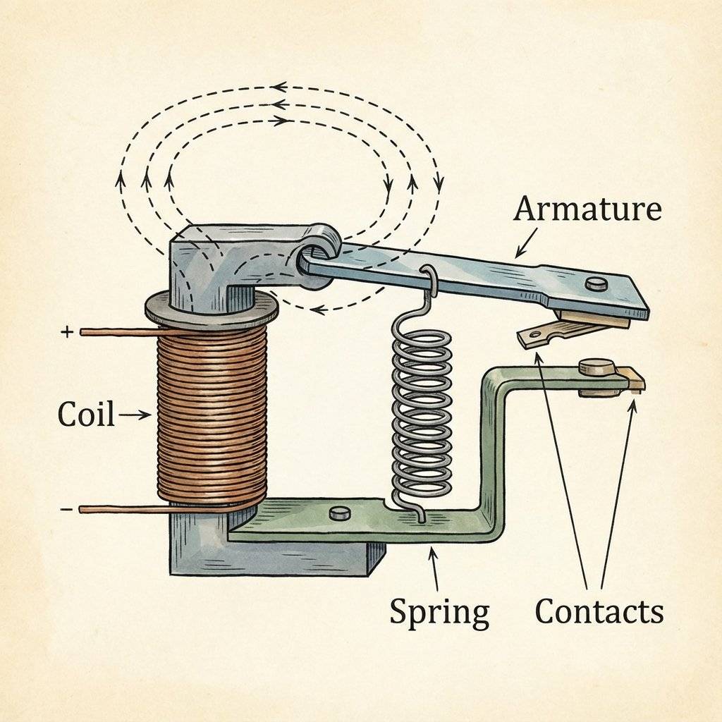
This is the most important concept of the day. Inside a Relay, the Coil Circuit (Arduino side) and the Contact Circuit (High Voltage side) are physically separated. There is no wire connecting them. They are separated by air and plastic. This is called Galvanic Isolation.
If a lightning bolt hits your desk lamp, it might melt the Relay Contacts. But it cannot travel back to your Arduino because there is no path. The relay sacrifices itself to save the microcontroller.
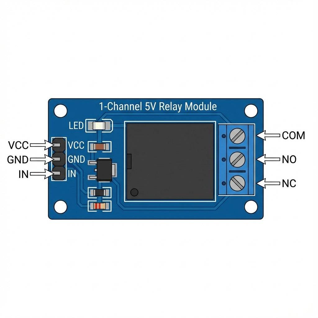
Do not buy a “bare” relay component. Relays need a lot of current (70mA+) to energize the coil. The Arduino pins can only give 40mA. (Remember Day 17: “Brain vs Muscle”). So, we use a Relay Module. This module contains:
A single relay consumes about to when active. The Arduino’s pin can supply about total (if powered via USB).
If you are using a 4-Channel or 8-Channel Relay module, you MUST use an external power supply. If you try to power 8 relays from the Arduino, the voltage will sag, and the Arduino will reset randomly.
We call software errors “Bugs”. Do you know why? In 1947, computer pioneer Grace Hopper was working on the Harvard Mark II computer. It wasn’t made of silicon; it was made of thousands of Electromechanical Relays. The computer failed. They opened it up and found a real moth stuck between the contacts of Relay #70. The moth prevented the contacts from touching. She taped the dead moth into the logbook with the note: “First actual case of bug being found.” Every time your code fails, you are paying homage to that moth.
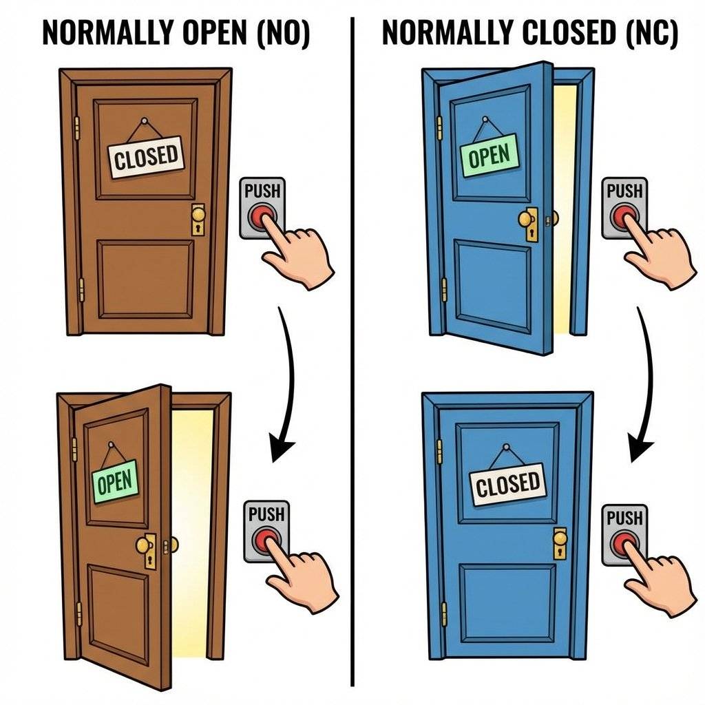
Relays have three high-voltage terminals. Understanding them is critical.
The Door Analogy:
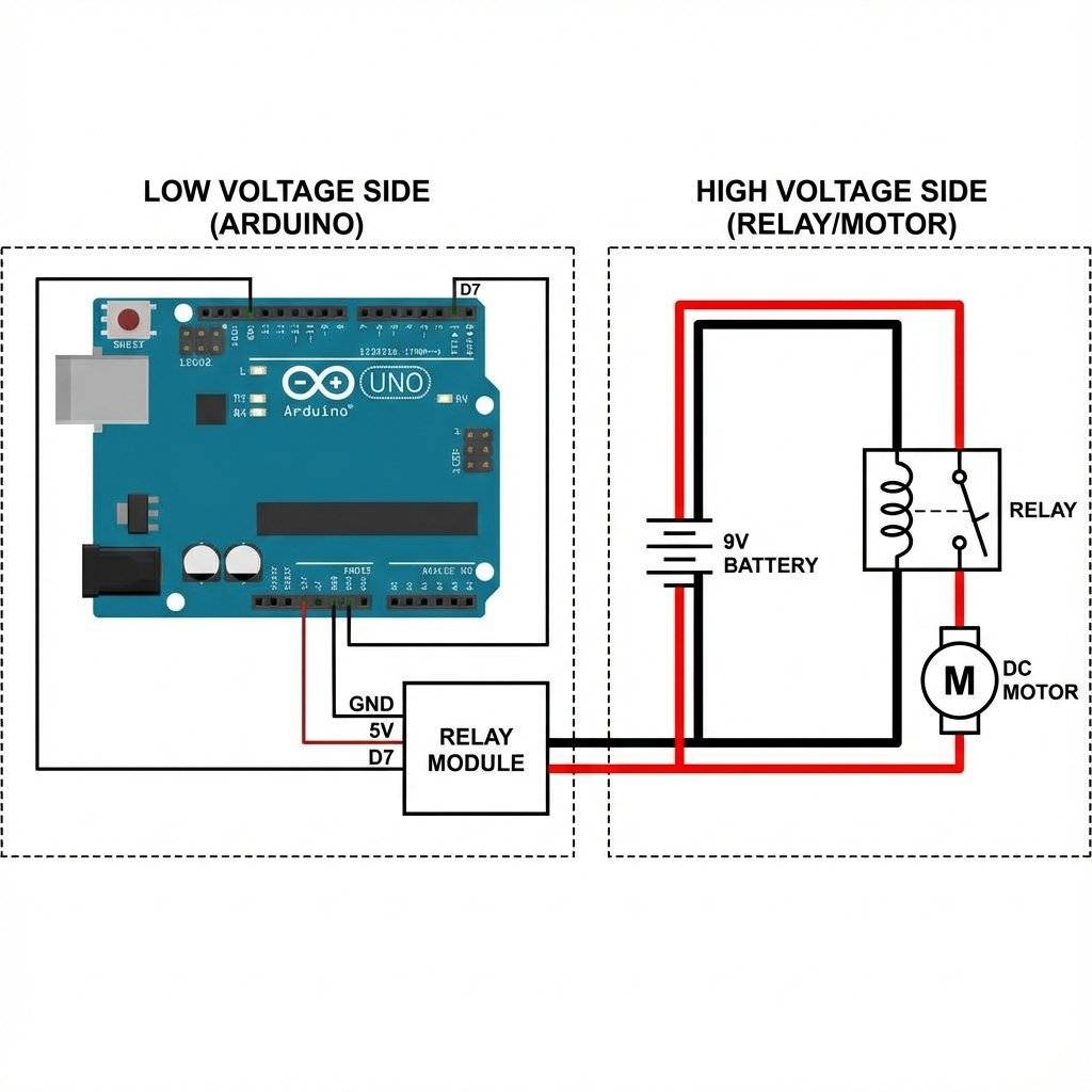
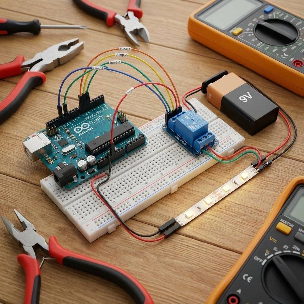
We will simulate a High Voltage lamp using a specialized setup. Components:
Wiring Instructions (Control Side):
Wiring Instructions (High Power Side):
Notice: The Battery Negative does NOT connect to Arduino GND here. Isolation is maintained!
The code is laughably simple.
Because the Relay Module has a transistor built-in, we just use digitalWrite.
const int relayPin = 7;

void setup() {
  pinMode(relayPin, OUTPUT);
  Serial.begin(9600);
  Serial.println("System Ready");
}

void loop() {
  Serial.println("Lights ON");
  digitalWrite(relayPin, HIGH); // CLICK!
  delay(2000);
Serial.println("Lights OFF");
  digitalWrite(relayPin, LOW); // CLACK!
  delay(2000);
}
Important Pro Tip: Cycle Protection Relays are mechanical. They have a physical lifespan (e.g., 100,000 cycles). If you write a bug in your code that toggles the relay 100 times a second:
Always implement a “Cooldown” timer in your logic. Don’t allow the relay to switch state more than once every 2 seconds.
unsigned long lastSwitchTime = 0;
const int COOLDOWN = 2000;

void toggleRelay() {
  if (millis() - lastSwitchTime > COOLDOWN) {
    // Safe to switch
    digitalWrite(relayPin, !digitalRead(relayPin));
    lastSwitchTime = millis();
  }
}
Troubleshooting: The “Active Low” Trap
Some Relay Modules are “Active Low”.
This means LOW turns them ON, and HIGH turns them OFF.
It works backwards.
If your relay starts ON when you expect OFF, just swap your HIGH/LOW logic.
digitalWrite(relayPin, !state);
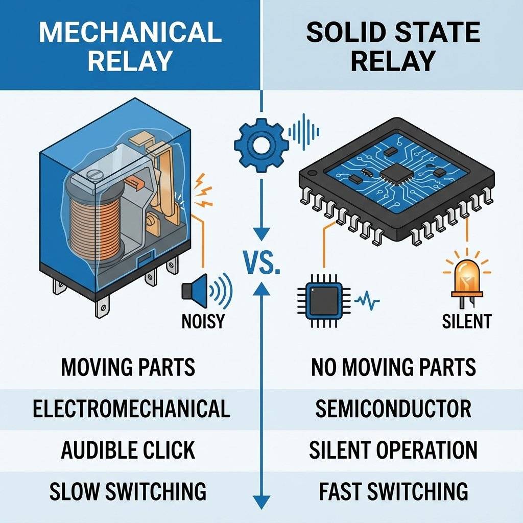
Mechanical relays are great, but they have flaws:
The Solution? The Logic Relay. SSR (Solid State Relay). It uses massive internal SCRs or Triacs (Silicon).
For dimming lights? Use an SSR. For turning on a water pump once a day? Use a Mechanical Relay.
You will encounter many relays in your career.
When you switch off an AC load (like a Fan), it creates a voltage spike (Inductive Kickback), just like our DC motor yesterday. In AC, this causes Arcing across the Relay contacts. It looks like blue lightning inside the plastic box. This melts the contacts and they might weld shut (Stick ON).
The Fix: A Snubber Network. A Resistor () and a Capacitor () in series, placed across the relay contacts. It absorbs the arc. Many high-quality relay modules come with Snubbers built-in.
You have:
Combine them. Mode 1: Push Button -> Toggle Light (Manual Override). Mode 2: If Dark -> Turn ON Light (Auto).
const int button = 2;
const int relay = 7;
const int ldr = A0;
bool manualMode = false;

void loop() {
  if (digitalRead(button) == HIGH) {
    manualMode = !manualMode; // Toggle Mode
    delay(500); // Debounce
  }
if (manualMode) {
    // Just toggle relay logic here
  } else {
    // Auto Mode
    if (analogRead(ldr) < 300) digitalWrite(relay, HIGH);
    else digitalWrite(relay, LOW);
  }
}
Here is a “Magic Trick” you can do with relays. You can create a circuit that “Remembers” it is ON, even after you release the button. This is how elevator buttons worked in the 1920s.
The Concept:
This is the grandfather of the Silicon Flip-Flop (Bit Memory).
Look closely at the text printed on your blue relay. It usually says: .
: This is the Absolute Maximum for AC.
: This is the limit for DC.
Notice the Voltage is much lower ().
Why is DC so dangerous? When you open a switch, the electricity wants to keep flowing. It ionizes the air, creating a plasma bridge (an Arc).
If you look at your Relay Module, you might see a yellow jumper connecting VCC and JD-VCC.
Risk: Current spikes from the coil might reset the Arduino.
Remove the jumper.
Connect Arduino to VCC.
Connect External Power Supply to JD-VCC and GND.
Do NOT connect Arduino GND to Module GND.
Now, the Arduino only powers the Optocoupler LED (tiny current). The External supply does the heavy lifting.
This provides Total Galvanic Isolation. The Arduino is electrically invincible.
Diagnostic Trick: The Flashlight Test How do you know if your relay module is truly isolated? Look at the circuit board. Find the black chip with 4 legs (usually an EL817 or PC817). Trace the traces. If there is a clear “Gap” on the PCB where no copper crosses (except under that chip), you have an isolated module. Cheap modules often skip this. Always check the PCB layout.
One day, your relay will fail.
You will send digitalWrite(LOW), you will hear the “Clack”, but the light will stay ON.
Why?
The metal contacts have Welded together.
This happens if you switch a load that has a huge “Inrush Current” (like a large motor or a cheap LED driver). The spark melted the metal, and they fused.
The Fix:
| Component | Quantity | Value | Notes |
|---|---|---|---|
| Arduino Uno | 1 | Any | The Brain. |
| Relay Module | 1 | 5V 1-Channel | Ensure it says “5V DC” on the coil. |
| Jumper Wires | 10 | M-F | Male-to-Female wires are needed. |
| Load | 1 | DC Motor/LED | A safe low-voltage test load. |
| Power Supply | 1 | 9V/12V | To power the Load. |
| Screwdriver | 1 | Small Philips | To tighten the terminals. |
| Wire Stripper | 1 | Any | To strip the ends of thick wires. |
| Sound Sensor | 1 | KY-037 | Optional: For “Clapper” logic. |
| Multimeter | 1 | Any | To verify Voltage before connecting. |
You have mastered the Switch.
You now possess the ability to control literally any electrical device in your home.
The barrier between “Digital Code” and “Physical Reality” is gone.
You can write a if() statement that turns on your coffee machine.
Tomorrow, on Day 19, we look at the Fourth Dimension.
Time.
We will learn how to make our projects aware of the exact time and date.
We are building a Real Time Clock (RTC).
No more delay(1000). We are going to schedule events.
See you on Day 19.

Combine sensors and servos to build a real-time scanning radar. Learn Polar Coordinates, Serial Plotting, and data visualization.
Read More →
Turn your Arduino into a robotics controller. Master the SG90 Servo Motor, understand closed-loop control systems, and build precise robotic joints.
Read More →
Give your robot eyes. Learn how the HC-SR04 Ultrasonic Sensor works, master the physics of sound, and build a precision Parking Sensor using Arduino.
Read More →