Build a Working Radar: Mapping Rooms with Arduino, Ultrasonics, and Servos
Combine sensors and servos to build a real-time scanning radar. Learn Polar Coordinates, Serial Plotting, and data visualization.
Read More →
* SYSTEM.NOTICE: Affiliate links support continued laboratory research.
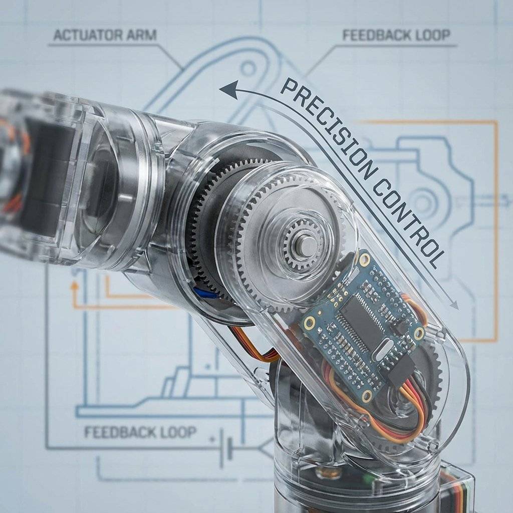
This is the cornerstone of every robotic arm, walking hexapod, and camera gimbal you have ever seen. To master it, we must leave the world of simple High/Low signals and enter the world of Closed Loop Control.
An SG90 Micro Servo looks like a tiny blue box. But inside, it is a marvel of engineering. It interacts with 4 distinct components packed into that tiny shell:
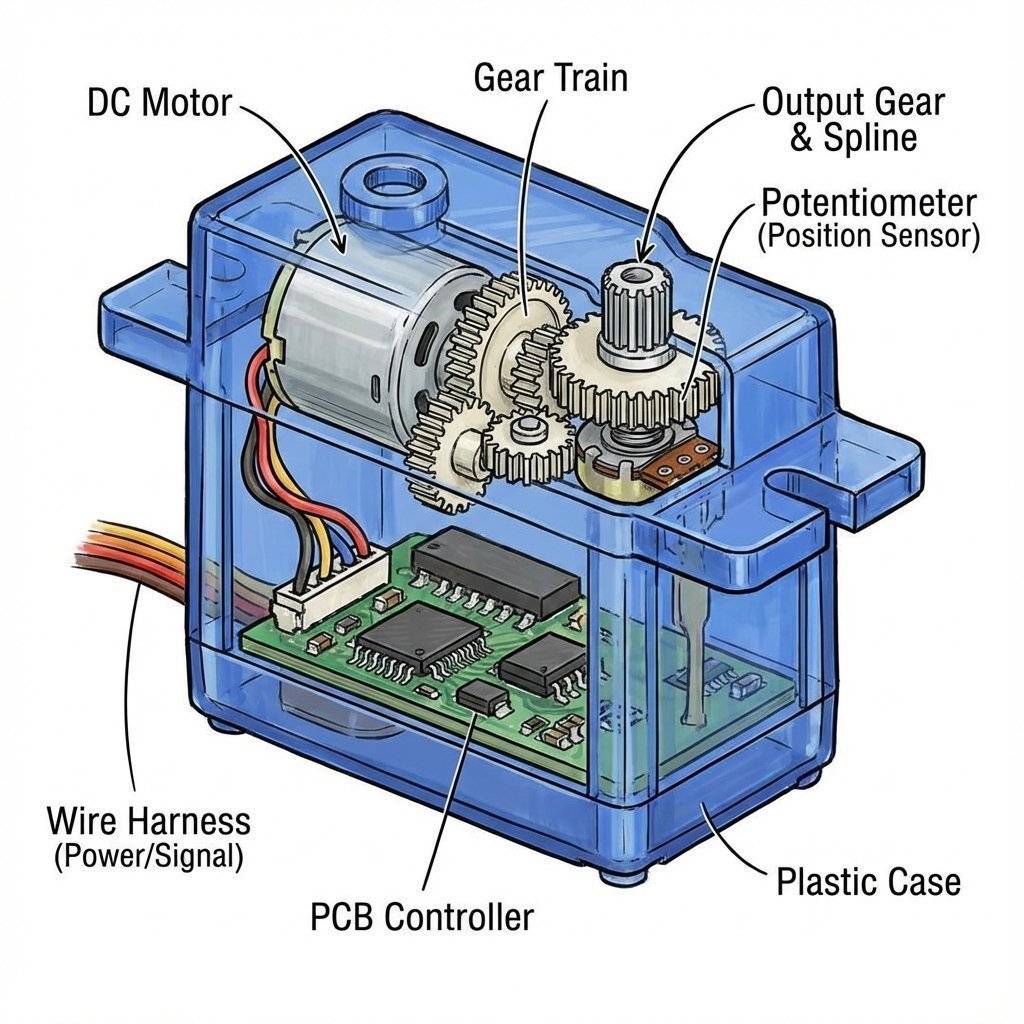
This is the magic. When you tell a servo to go to 90 degrees:
The brain inside the SG90 is actually a tiny analog computer running a P-Controller (Proportional Controller).
If you try to force the arm back to 0 with your hand, the Potentiometer moves. The PCB notices: “Hey! I should be at 90, but I am at 80!” It powers the motor to push back against your hand. This is called Holding Torque. It fights you to stay in position.
How does the servo reverse direction? Does it use a relay? No. It uses a tiny H-Bridge circuit inside the chip (refer to Day 17). By rapidly switching four internal transistors, it can reverse the polarity of the DC motor instantly.
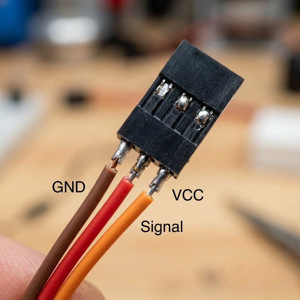
Servos always have 3 wires. The colors are standardized (usually).
Warning: Never plug the connector in backwards. It usually won’t break it instantly, but it won’t work. Double Warning: Never feed a servo more than . It will fry the internal PCB. is perfect.
Controlling a servo manually is hard (we will see why in the Deep Dive).
Luckily, Arduino has a built-in library that does the heavy lifting.
#include <Servo.h>
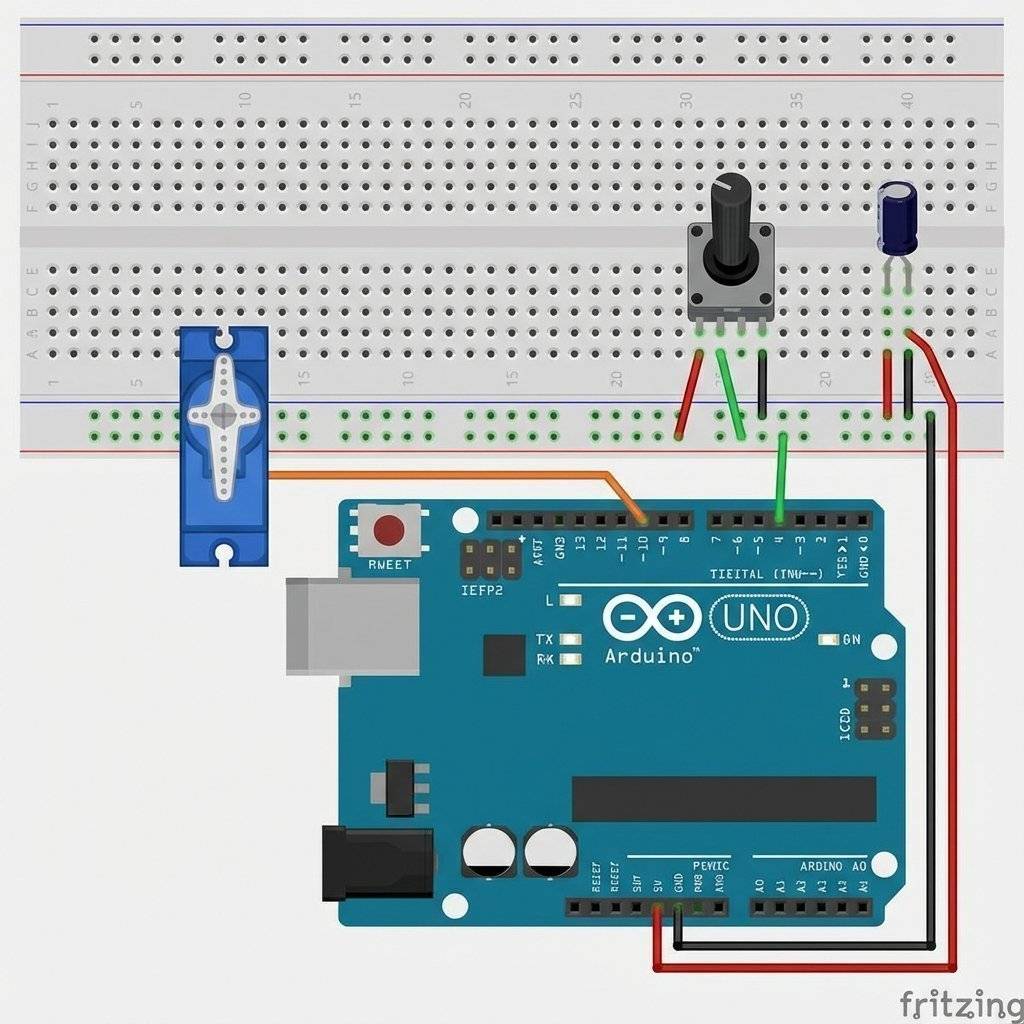
Let’s connect a Potentiometer (Day 14) and use it to control the Servo angle. Wiring:
The Code:
#include <Servo.h>

Servo myServo;  // Create a servo object

void setup() {
  myServo.attach(9); // Tell Arduino the servo is on Pin 9
}

void loop() {
  int potValue = analogRead(A0); // Read Pot (0 to 1023)
  // Map the value to an angle (0 to 180)
  int angle = map(potValue, 0, 1023, 0, 180);
  myServo.write(angle); // Tell servo to go to that position
  delay(15); // Wait for the servo to get there
}
Upload this. Turn the knob. The motor mimics your movement perfectly. Congratulations, you just built a Remote Manipulator.
map()Why did we use map()?
analogRead() gives us 0 to 1023.myServo.write() expects 0 to 180.
If you send myServo.write(500), the library will just clamp it to 180.
We need to scale the numbers down proportionally.
map(value, InLow, InHigh, OutLow, OutHigh) does accurately this math for us.
Wait, didn’t we learn PWM on Day 15?
We used analogWrite() to dim LEDs. That was 490Hz or 980Hz.
Servo PWM is different.
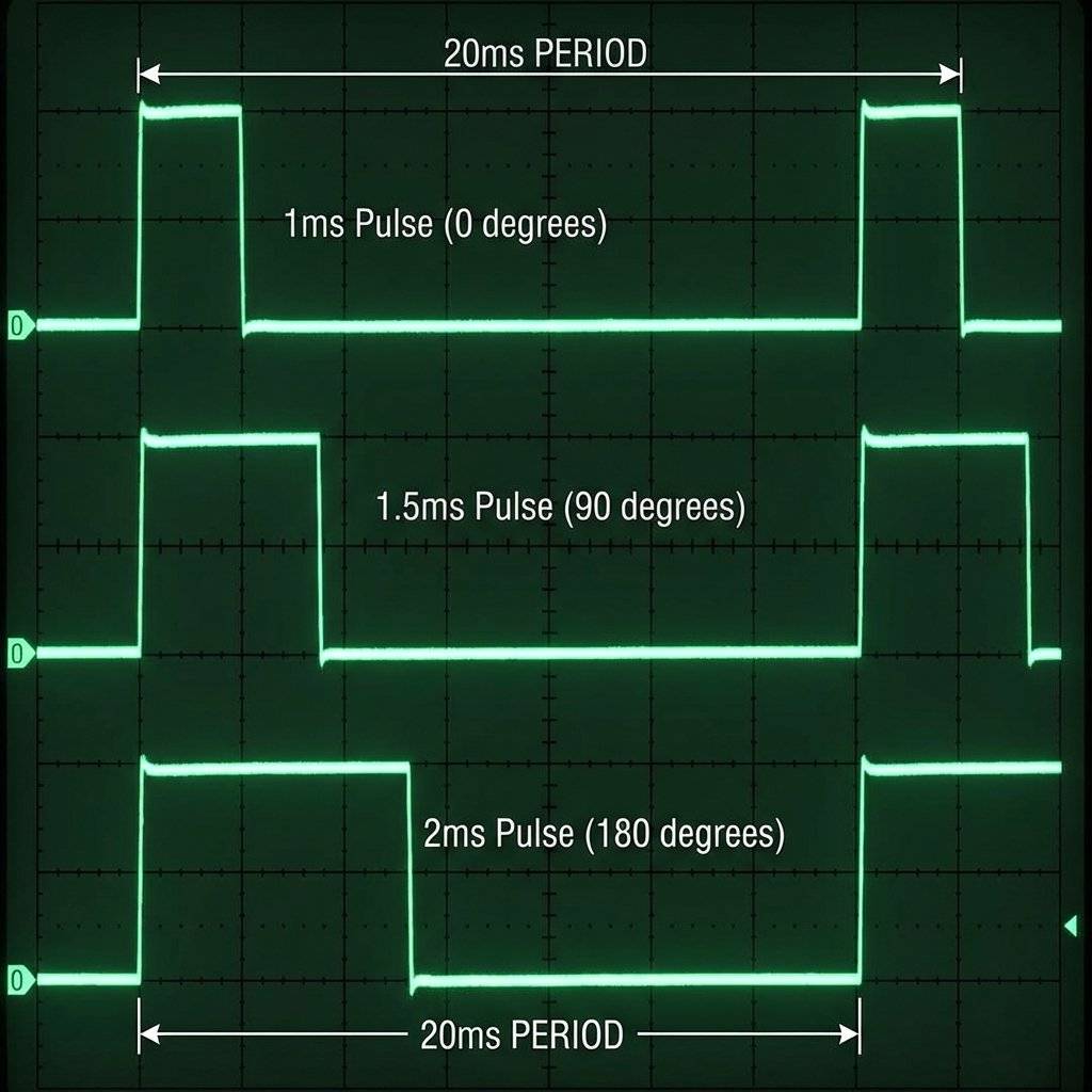
It runs at 50Hz (50 times a second). The period is 20ms.
The angle is determined by the width of the HIGH pulse.
This is precise timing. If the wire is loose and the pulse stretches from 1.5ms to 1.6ms, the arm will jitter. This is why servos sometimes “twitch” if the connection is bad.
writeMicroseconds()The write(angle) function is easy, but it is “low resolution”.
It only lets you move in 1-degree steps.
What if you need to aim a laser at 90.5 degrees?
Use myServo.writeMicroseconds(us).
Instead of angles (0-180), you send the raw time (1000 to 2000).
myServo.write(90) is the same as myServo.writeMicroseconds(1500).myServo.write(91) is roughly myServo.writeMicroseconds(1511).
But you can type myServo.writeMicroseconds(1505)!
This gives you 10x more precision.
For robotic arms, always use microseconds. For waving a flag, use degrees.Why is the standard 50Hz? Why 1ms to 2ms? It comes from Model Aviation in the 1960s. Radio Control (RC) planes needed a way to control flaps and rudders wirelessly. The analog radios of the time found it easy to send a “Pulse Train” where the width of the pulse represented the stick position. The components chosen for the receiver decoders (decades before Arduinos existed) just happened to work best with a 20ms refresh rate. The entire robotics industry today follows this 60-year-old standard invented by hobbyists flying balsa wood planes. It is a legacy standard, but it is so robust that it refuses to die.
Beginners often ask: “Which motor should I use?” Let’s settle this once and for all.
DC Motor (Day 17): Pro: Fast, Strong, Simple.
Con: Dumb. No position control. You don’t know where it is.
Use for: Wheels, Fans, Drills.
Servo Motor (Day 22): Pro: Precise Angle (0-180). Smart. High Torque.
Con: Limited range (usually can’t spin 360). Slower rpm.
Use for: Robot Arms, Steering, Grippers, Gimbals.
Stepper Motor (Phase 5): Pro: Precise Rotation (infinite spin). Extremely accurate control of speed and distance.
Con: Complex driver needed. Low efficiency.
Use for: 3D Printers, CNC Machines.
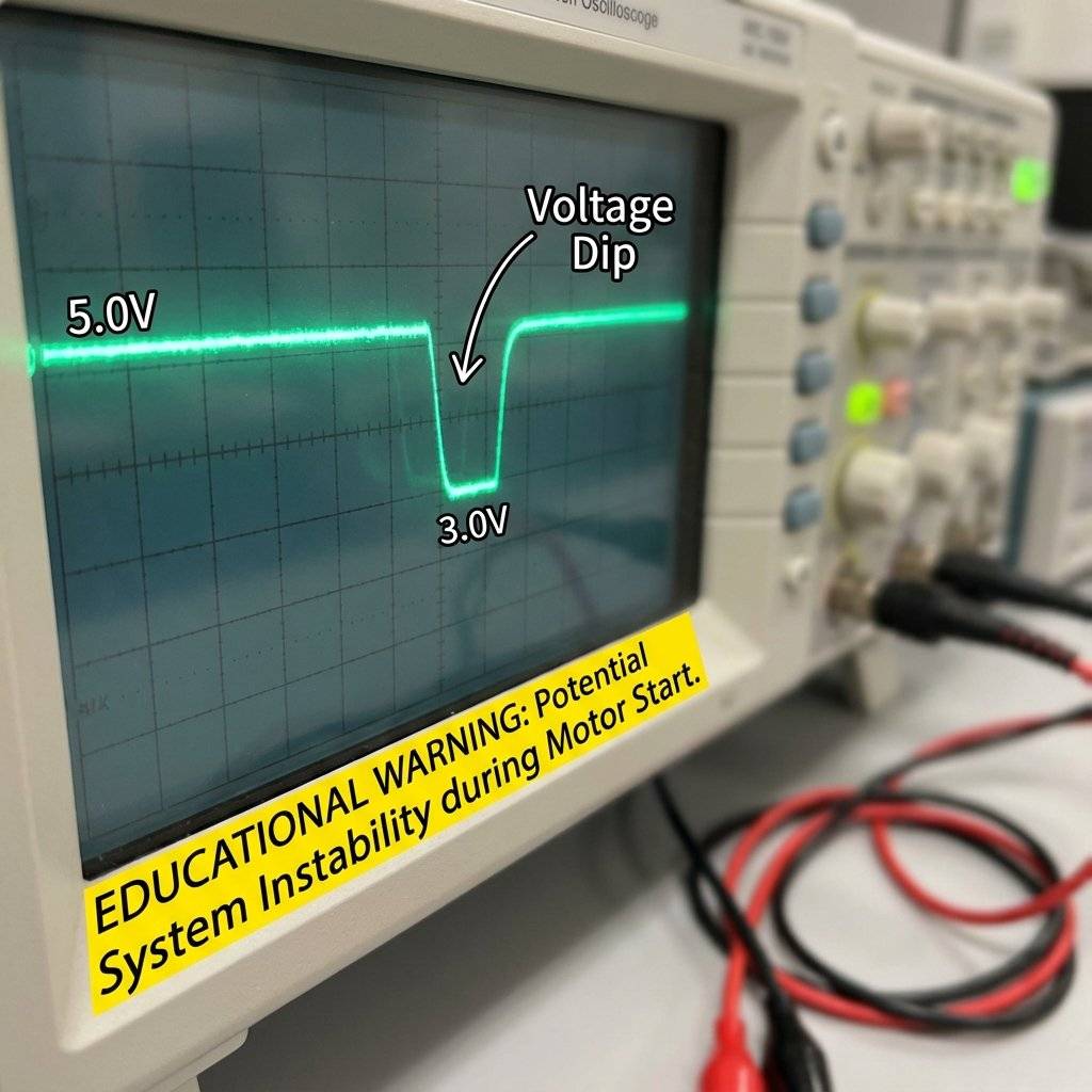
The #1 problem beginners face with Servos: The Arduino Resets. You move the motor, and the Arduino reboots. Why? Power Starvation. When a servo starts moving, it draws a massive spike of current (Inrush Current). Sometimes it draws 500mA or more. If the USB port cannot supply enough juice, the 5V rail voltage dips down to 3.5V. The Arduino’s brain needs 4.5V to think. It blacks out (Brownout) and resets.
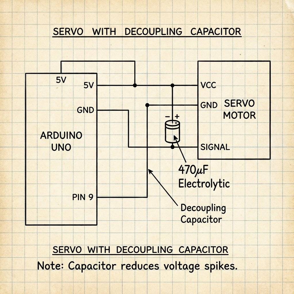
We need a backup battery tank. We place a large Electrolytic Capacitor (470uF or 1000uF) across the power rails (+ and -) near the servo. When the servo demands a spike of power, the capacitor dumps its stored energy to fill the gap. It smooths out the voltage dips and keeps the Arduino alive. Rule: If you use more than 2 servos, ALWAYS use an external 5V power supply (like 4xAA batteries). Do not power them from the Arduino 5V and USB.
Sometimes, your servo will sit at 90 degrees and make a high-pitched whine. eeeeeeeeeeeeee This happens when the physical arm is almost at the target, but not quite. Maybe gravity is pulling it down by 0.1 degrees. The Feedback loop fights back: “Go Up!” Gravity pulls: “Go Down!” It oscillates at high speed. The Fix:
myServo.detach() to stop the signal. The motor will relax (and the whine stops).What happens if you tell the servo to go to 180, but you block it with your hand? The PCB sees “Error” -> “Full Power!” The motor draws Stall Current (often 1 Amp for a tiny SG90).
Now that you have motion, what can you build?
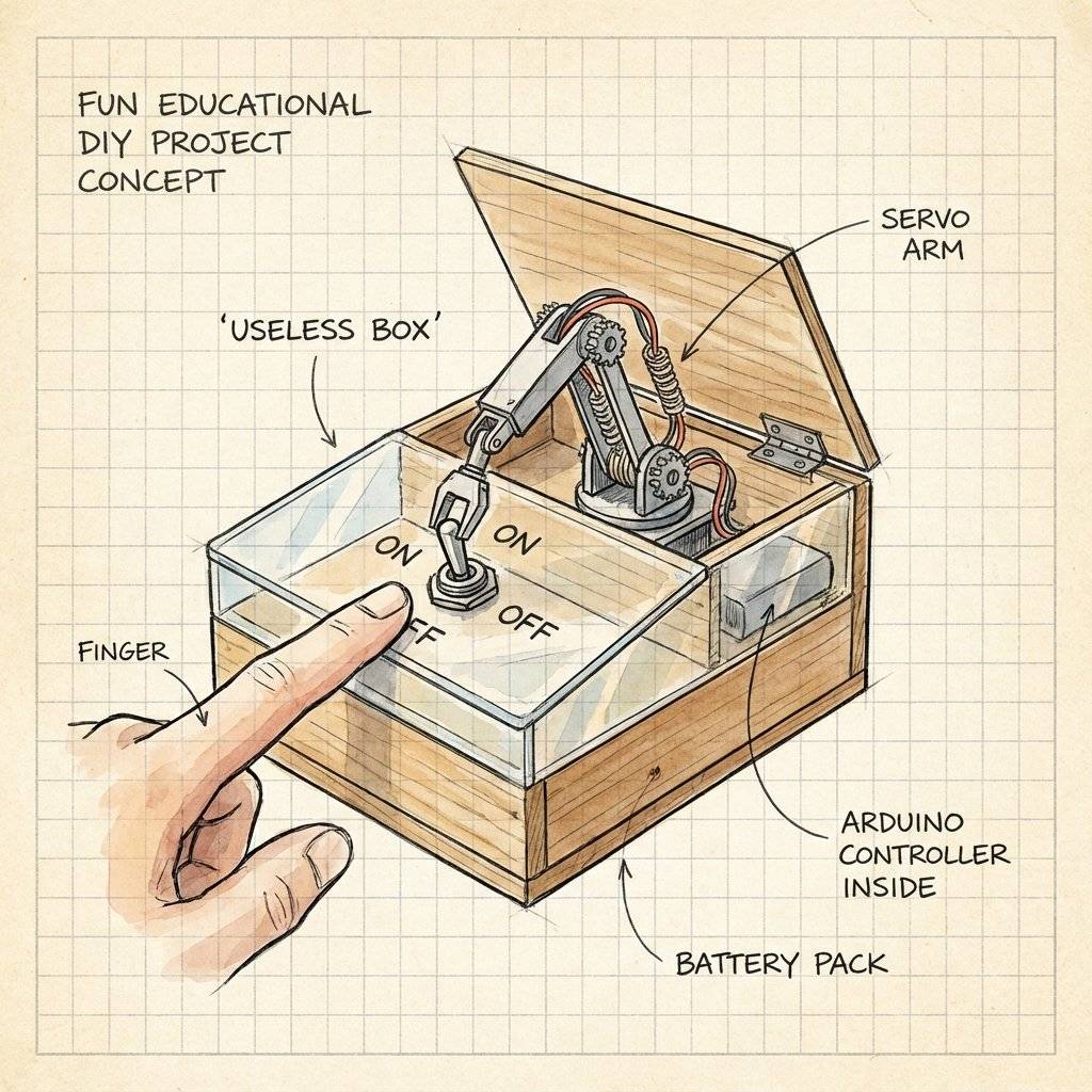
This is a classic internet meme project. A box with a switch. When you flip the switch ON… A servo arm pops out of the box… …and flips the switch OFF. Then it goes back inside. It is a machine with the sole purpose of turning itself off. It requires: 1 Servo, 1 Switch, and some cardboard engineering.
Using 3 servos per leg, and 6 legs… you need 18 servos. You can make a spider that walks over rough terrain. This requires a dedicated Servo Driver Board (like the PCA9685) because the Arduino Uno doesn’t have enough pins. We will cover I2C Servo Drivers in Phase 5.

This is the “Hello World” of 2-axis control. You mount one servo horizontally (Pan) and glue a second servo on top of it vertically (Tilt). Now you have a turret.
Servo panServo;
Servo tiltServo;
void setup() {
  panServo.attach(9);
  tiltServo.attach(10);
}Every arm needs a hand. A “Parallel Gripper” uses a single servo to open and close two jaws.
The white plastic arm that snaps onto the motor is called the Horn. The jagged metal/plastic shaft it connects to is the Spline. Crucial Advice:
Why are robot arms always short? Because of Torque. The SG90 is rated for 1.8 kg-cm. This means:
The standard Servo library moves at maximum speed.
myServo.write(180) teleports the arm as fast as physics allow.
What if you want a slow, cinematic move?
You have to write a for loop with delays.
// Slowly move from 0 to 180
for (int pos = 0; pos <= 180; pos += 1) {
  myServo.write(pos);
  delay(15); // Adjust this delay to change speed
}
If you hate writing loops, install the VarSpeedServo library.
It lets you do: myServo.write(180, 30); (Angle 180, Speed 30).
It handles the timing in the background (using Interrupts), so your code doesn’t freeze!
Sometimes you buy a servo that looks like an SG90, but it spins 360 degrees forever. This is a Continuous Rotation Servo. It is NOT a normal servo. It is a DC Motor with a brain transplant. The manufacturer has:
Removed the physical stopper from the gear.
Replaced the Potentiometer with two fixed resistors (tricking the brain into thinking it is ALWAYS at 90 degrees). How to control it:
write(90): Stop. (Brain thinks it’s at the target).
write(180): Full Speed Forward. (Brain thinks “I’m at 90, I need to get to 180, Go Fast!”).
write(0): Full Speed Backward.
You lose Position Control, but you gain a high-torque geared motor that needs no driver shield.
Perfect for wheels on a small robot.
| Component | Quantity | Value | Notes |
|---|---|---|---|
| Arduino Uno | 1 | Any | The Brain. |
| SG90 Micro Servo | 1 | 9g | 180° rotation. |
| Potentiometer | 1 | For manual control. | |
| Capacitor | 1 | 470µF-1000µF | Decoupling / Power Smoothing. |
| Jumper Wires | 10 | M-M/M-F | Connectivity. |
| Battery Pack | 1 | 4xAA (6V) | Recommended for multiple servos. |
You have mastered the muscle. You understand that a servo is not just a motor; it is a smart feedback system. You know how to control it, and more importantly, how to power it safely without crashing your brain.
We have Eyes (Day 21). We have Muscles (Day 22). Tomorrow, Day 23, is special. We are going to combine everything. We are going to verify our skills with a Capstone Project. We will build a Radar Station that sweeps the area and displays targets on a screen. It will combine Ultrasonic, Servo, and Serial Communication.
Get your jumper wires ready. See you on Day 23.

Combine sensors and servos to build a real-time scanning radar. Learn Polar Coordinates, Serial Plotting, and data visualization.
Read More →
Give your robot eyes. Learn how the HC-SR04 Ultrasonic Sensor works, master the physics of sound, and build a precision Parking Sensor using Arduino.
Read More →
Master the Mechanical Relay. Learn how to control desk lamps, fans, and heavy appliances using an Arduino. Understanding NO, NC, and Galvanic Isolation.
Read More →