Motion Control: Master Arduino I2C and the MPU6050 Gyroscope
Learn how to read the MPU6050 Accelerometer and Gyroscope using the I2C protocol. Master registers, raw data, and build a digital spirit level.
Read More →
* SYSTEM.NOTICE: Affiliate links support continued laboratory research.
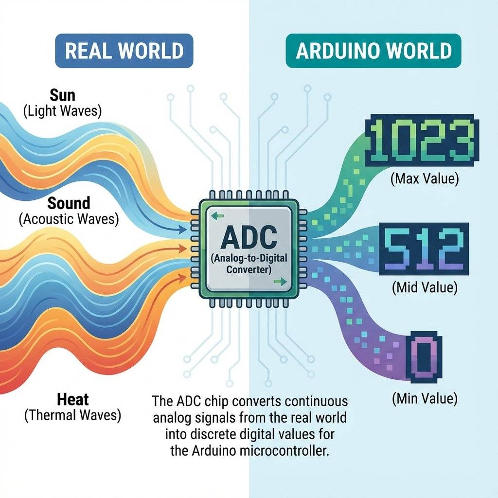
It was Black or White. Yes or No. But the real world isn’t digital. The real world is Analog. The temperature isn’t just “Hot” or “Cold”—it’s 23.4°C. The volume of music isn’t just “Mute” or “Max”—it’s a smooth slider. The light in a room varies from pitch black to blinding sun.
If we want our robots to interact with reality, they need to see these shades of gray. Today, we unlock the ADC (Analog to Digital Converter). We are going to teach the Arduino to read voltage.
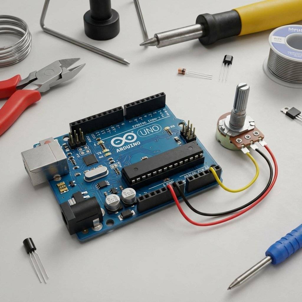
We met this component back in Day 6 (The Voltage Divider). A Potentiometer (or “Pot”) is a variable resistor. It has a knob. As you turn the knob, it changes resistance.
It has 3 legs.
Inside, there is a resistive track. The wiper slides along it.
It is a physical mechanical machine that creates an analog voltage.

The Arduino’s processor (ATMega328P) is digital. It only understands 1s and 0s. It cannot understand “2.5 Volts”. So, it has a special translator module called the ADC.
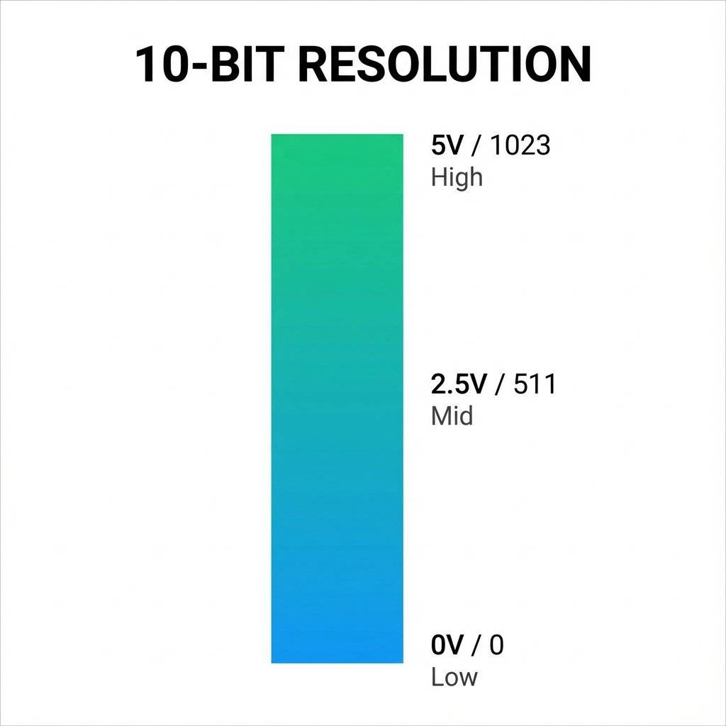
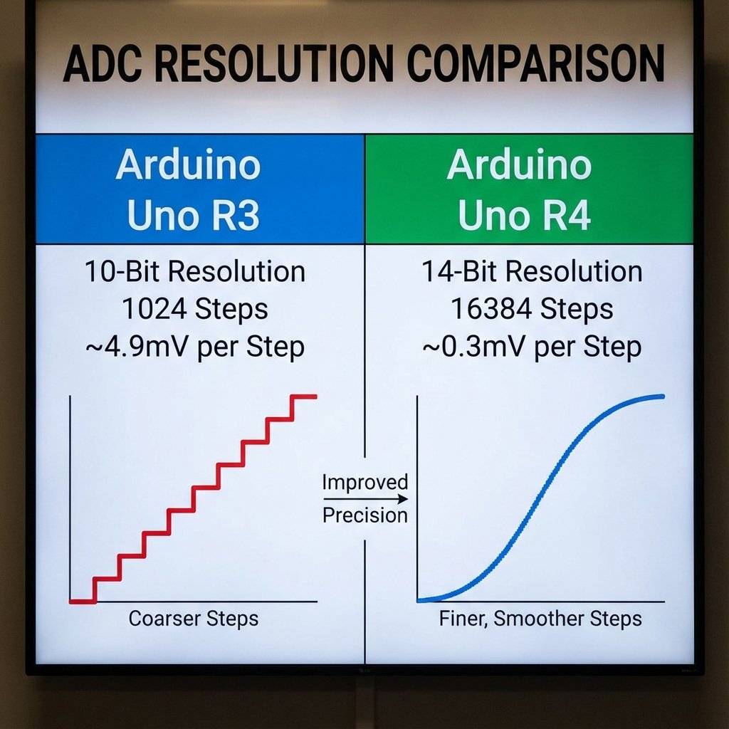
The ADC measures the voltage on a pin (A0 to A5) and converts it into a number. But what number? The standard Arduino Uno (R3) has a 10-bit ADC. This means it splits 5 Volts into steps.
Every step represents about 4.9 millivolts (5V / 1024).
analogRead()Reading this value is absurdly easy.
int sensorValue = analogRead(A0);
That’s it.
sensorValue will now hold a number between 0 and 1023.
Since we don’t have a screen on the Arduino, how do we know what the value is? We use the Serial Monitor. It allows the Arduino to send text back to your computer via the USB cable.
// Day 14: Analog Read Test

void setup() {
  // Start serial communication at 9600 bits per second
  Serial.begin(9600);
}

void loop() {
  // Read the input on analog pin 0:
  int sensorValue = analogRead(A0);
  // Print out the value:
  Serial.println(sensorValue);
  // Wait a bit so we aren't flooded with data
  delay(100);
}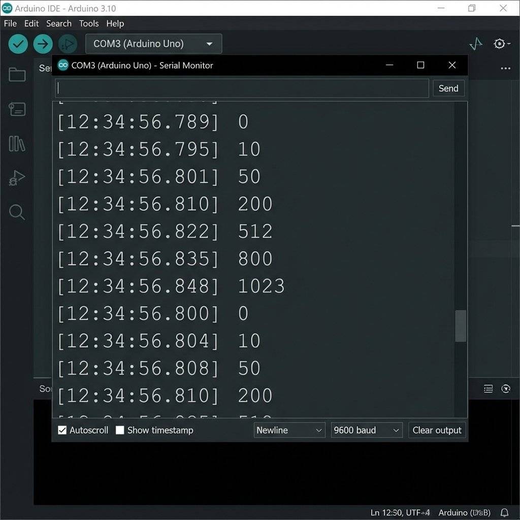
Seeing numbers is boring. Let’s make them do something.
Let’s use the knob to control the speed of a blinking LED.
Remember delay(1000)?
What if we replaced 1000 with our sensorValue?
void setup() {
  pinMode(13, OUTPUT);
}

void loop() {
  int speed = analogRead(A0); // Read the knob (0-1023)
  digitalWrite(13, HIGH);
  delay(speed); // Wait for 0ms to 1023ms
  digitalWrite(13, LOW);
  delay(speed);
}
Try it.
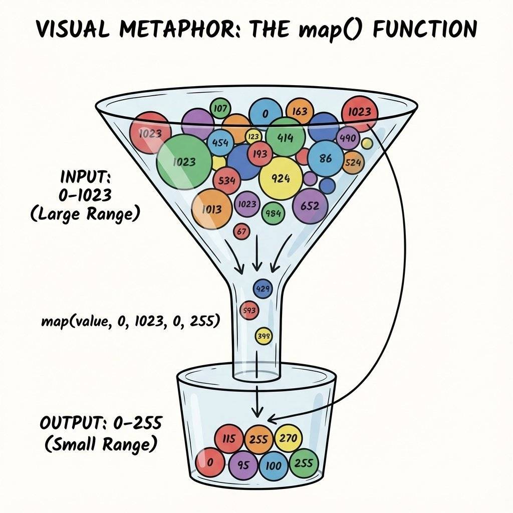
map() FunctionThere is a problem. The ADC gives us 0 to 1023. But what if we want to control an LED’s brightness (which we will learn tomorrow uses 0-255)? Or what if we want to control a Servo motor (0 to 180 degrees)?
We need to compress the range.
We could do math: value / 4.
But Arduino has a magic function called map().
output = map(value, fromLow, fromHigh, toLow, toHigh);
Example: Convert Potentiometer (0-1023) to Percentage (0-100).
int percent = map(sensorValue, 0, 1023, 0, 100);
This performs the linear interpolation for you.
It works backwards too!
int reverse = map(sensorValue, 0, 1023, 100, 0);
(Turning the knob right makes output go down).
You know those bouncing bars on a stereo system? You can build one. Hardware:
Potentiometer on A0.
5 LEDs on Pins 2, 3, 4, 5, 6. Software Logic:
Read A0.
If value > 100, turn on LED 1.
If value > 300, turn on LED 2.
If value > 500, turn on LED 3.
… This is basically a “Battery Level Indicator”. Try to code it using an Array (from Day 13) to keep it clean!
It was invented by Thomas Edison in 1872. (Or at least, he improved the rheostat design significantly). The name comes from “Potential” (Voltage) and “Meter” (Measure). Originally, it was used to calibrate telegraph lines. Today, 150 years later, the design is almost identical. A wiper sliding on Carbon. If it isn’t broken, don’t fix it.
map() TrapA warning about the map() function.
It uses Integer Math.
It chops off decimals.
If you try map(val, 0, 1023, 0, 5), and the result should be 2.8, map will give you 2.
It does not round up. It just deletes the decimal.
If you need precision, do the math manually using float.
Sometimes you want to know the actual voltage, not just a number from 0-1023.
How do we reverse the math?
Why the .0?
Because in C++, dividing integers (5/1023) results in zero.
You must use Floating Point numbers.
If sensorValue is 512:
Volts.
Go look at your potentiometer. Does it say B10K or A10K?
Let’s combine logic (Day 7) with analog sensing. We want an LED to turn on automatically if it gets dark. (Pretend the Potentiometer is an LDR light sensor for now).
int threshold = 300; // The "Darkness" limit

void loop() {
  int lightLevel = analogRead(A0);
  if (lightLevel < threshold) {
    digitalWrite(13, HIGH); // Turn on lights!
  } else {
    digitalWrite(13, LOW);  // Save energy
  }
}
This is a Threshold Trigger. Every smart device uses this logic. The thermostat triggers only when temp < 18°C. Analog Input -> Digital Decision.
Remember how we said analogRead can be jumpy?
If your numbers are bouncing (510, 515, 509, 512), you can smooth them out using software.
It’s called Averaging.
Instead of taking 1 reading, take 10 readings and divide by 10.
long total = 0;
for (int i = 0; i < 10; i++) {
  total = total + analogRead(A0);
  delay(1);
}
int average = total / 10;
This simple code makes your knob feel “Heavy” and smooth, like a luxury car volume dial.
Have you ever used a PS5 or Xbox controller? The thumbsticks? They are just Two Potentiometers stuck together.
You might have noticed a pin on the Arduino called AREF (Analog Reference).
By default, the ADC compares input voltage to 5V.
But what if you are measuring a sensor that only outputs 0-3.3V?
You are wasting the top range of your ADC bits.
You can connect 3.3V to the AREF pin and tell Arduino: “Use THIS as the ceiling, not 5V.”
analogReference(EXTERNAL);
This increases your precision significantly.
Warning: If you use EXTERNAL reference, and you accidentally touch 5V to the analog pin… you destroy the ADC. Use with caution.
Now that you know analogRead(), you can read ANY sensor that outputs 0-5V.
Here is your shopping list for the future:
LDR (Light Dependent Resistor): Dark = High Resistance. (Day 16).
Thermistor: Heat = Low Resistance.
Flex Sensor: Bent = High Resistance. (Used in Power Gloves).
Force Sensitive Resistor (FSR): Squeeze = Low Resistance.
Hall Effect Sensor: Magnet = Voltage.
Piezo Element: Vibration = Voltage Spike. They all work exactly the same way.
Build a Voltage Divider.
Connect middle to A0.
analogRead(A0).
You have unlocked the physical world.
Try this experiment.
randomSeed(analogRead(A0))).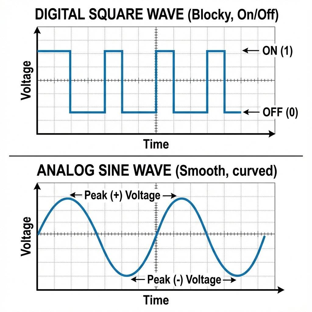
Don’t trust the code blindly.
If analogRead says “512”, get your multimeter (Day 3).
Put the black probe on GND and the red probe on the Wiper (Leg 2).
It should read 2.50V.
If it reads 2.50V but Arduino says “900”, your reference voltage (5V USB) might be fluctuating.
This happens often when running off laptop USB power. The “5V” is often actually 4.7V.
This causes ADC errors. For precision, use an external 9V power supply.
If you have the new Arduino Uno R4, you have a superpower.
The R4 has a 14-bit ADC.
steps.
While the R3 can only detect changes of 4.9mV.
The R4 can detect changes of 0.3 millivolts.
This allows for extreme precision in scientific sensors.
However, by default, the R4 runs in 10-bit mode to remain compatible with old code. You have to unlock the 14-bit mode manually (analogReadResolution(14)).
| Component | Quantity | Value | Notes |
|---|---|---|---|
| Arduino Uno | 1 | R3 or R4 | The Brain |
| Potentiometer | 1 | (B10K) | The Sensor |
| LED | 1 | Color | Output Indicator |
| Resistor | 1 | For LED | |
| Breadboard | 1 | Half+ | Prototyping |
You have opened the eyes of the machine.
Before today, your Arduino was blind.
Now, it can sense intensity.
Using analogRead, you can read:
Tomorrow, we do the opposite.
We have learned analogRead (Input).
Tomorrow, we learn analogWrite (Output).
But wait… digital pins can’t output 2.5V… or can they?
Get ready for PWM (Pulse Width Modulation) and the art of faking it.
See you on Day 15.

Learn how to read the MPU6050 Accelerometer and Gyroscope using the I2C protocol. Master registers, raw data, and build a digital spirit level.
Read More →
Give your circuits eyes and ears. Learn how to use Light Dependent Resistors (LDRs), Thermistors, and Microphones to control the physical world.
Read More →