Reading the World: Master Arduino Analog Inputs & Potentiometers
Digital is black and white. The real world is gray. Learn how to use the Arduino ADC to read potentiometers, sensors, and voltages using analogRead().
Read More →
* SYSTEM.NOTICE: Affiliate links support continued laboratory research.
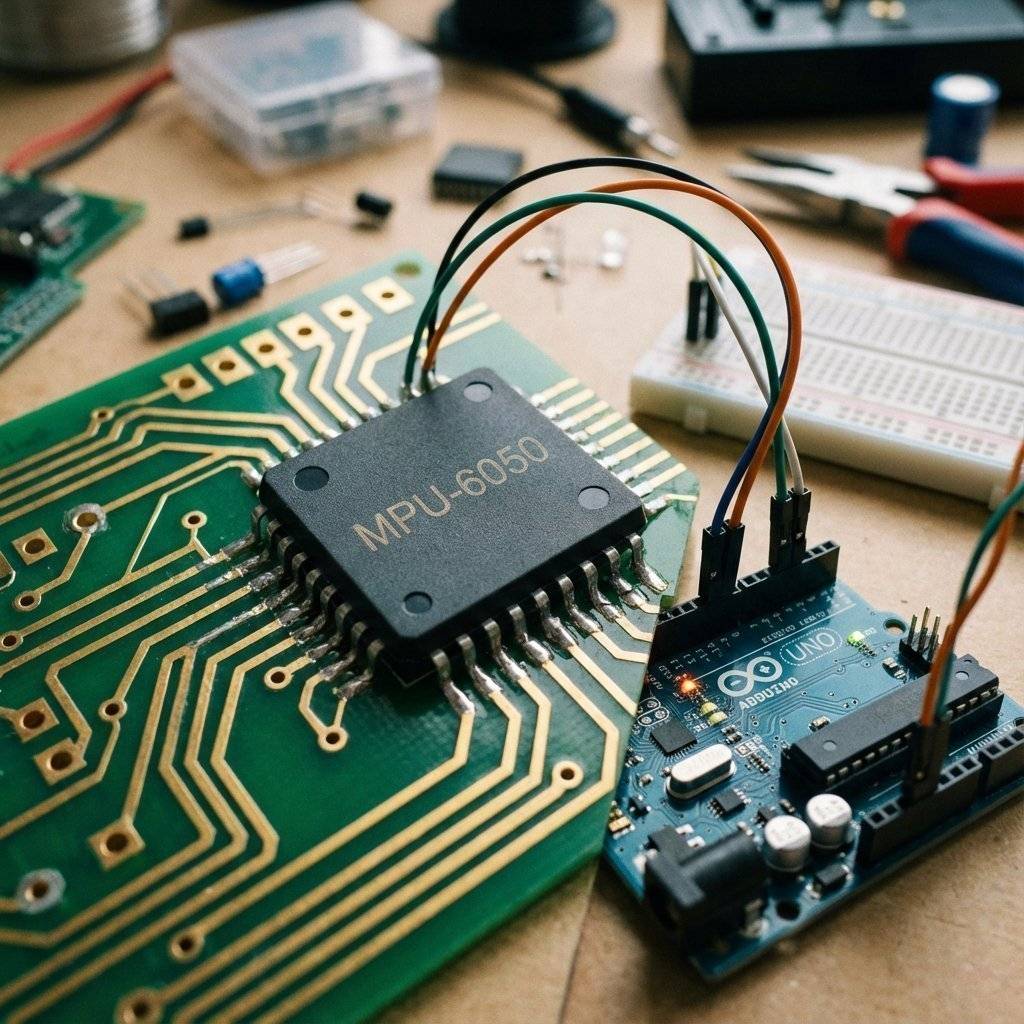
Today, we master the I2C Protocol and the MPU6050 Accelerometer/Gyroscope. This is the same technology inside your smartphone that detects when you rotate the screen.
Up until now, every pin had one job (LED, Button, Servo). But chips are complex. You can’t have 100 pins for 100 features. Engineers invented I2C (Inter-Integrated Circuit) to solve this. It is a Bus. Think of it like a telephone line. You can connect up to 127 devices to the same two wires.
The Arduino is the Master. The Sensors (Gyro, Screen, RTC) are the Slaves. The Master shouts a name (Address), and only that Slave answers.
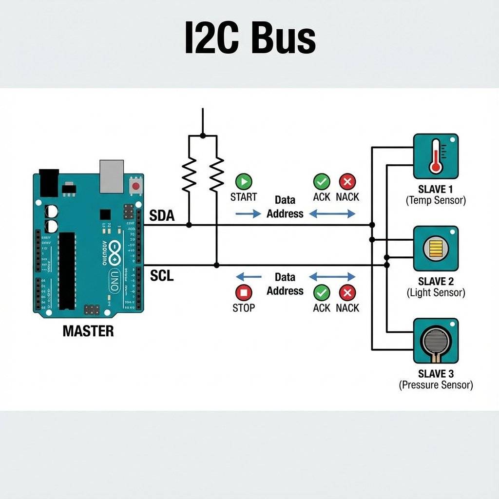
I2C is unique because the Master never pushes 5V onto the line. It only pulls it to GND (0V) or “Lets go” (Float). This is called Open Drain. To get 5V, we need Pull-Up Resistors (usually ) connected to VCC.
Why do we usually see resistors? It’s a balance.
Wire library enables the internal pull-ups, but they are weak (). For robust robots, ALWAYS add external 4.7k resistors.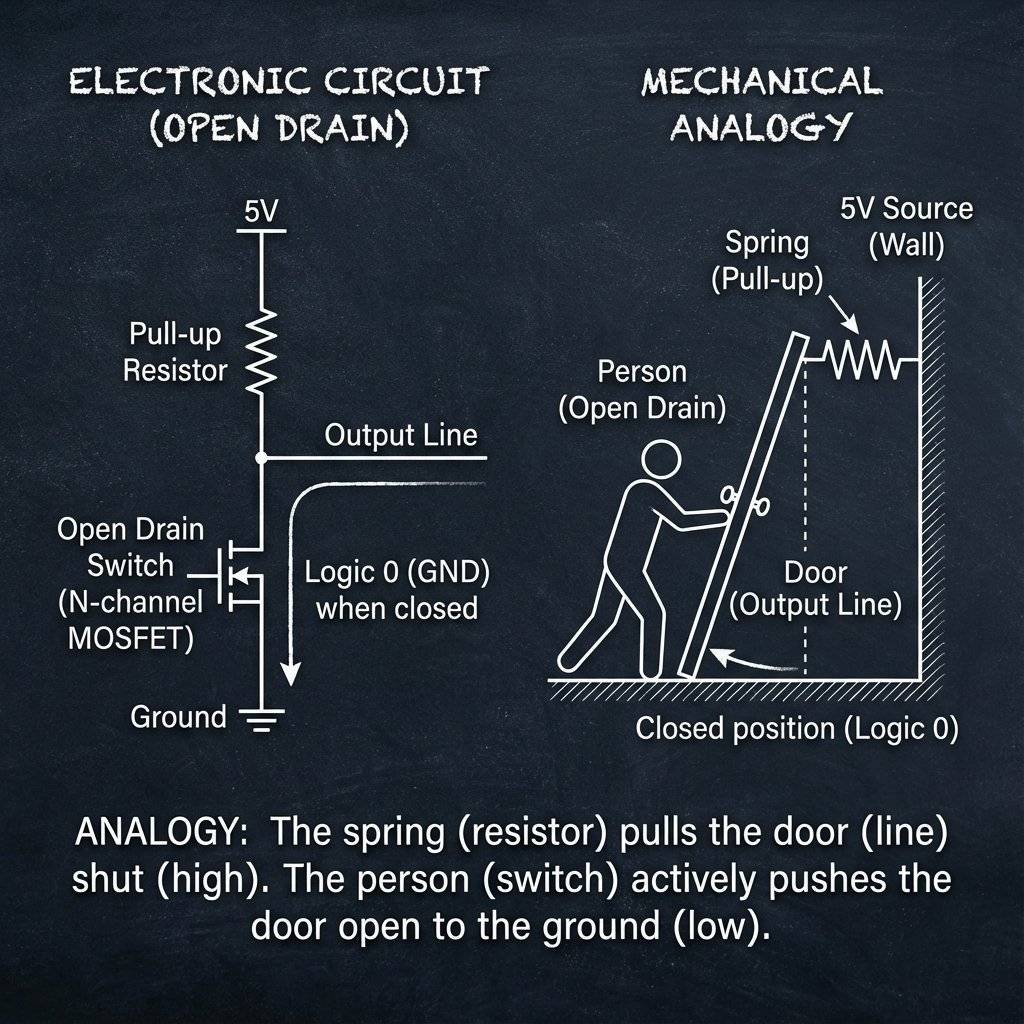
This little blue chip is a beast. It contains:
Pinout:
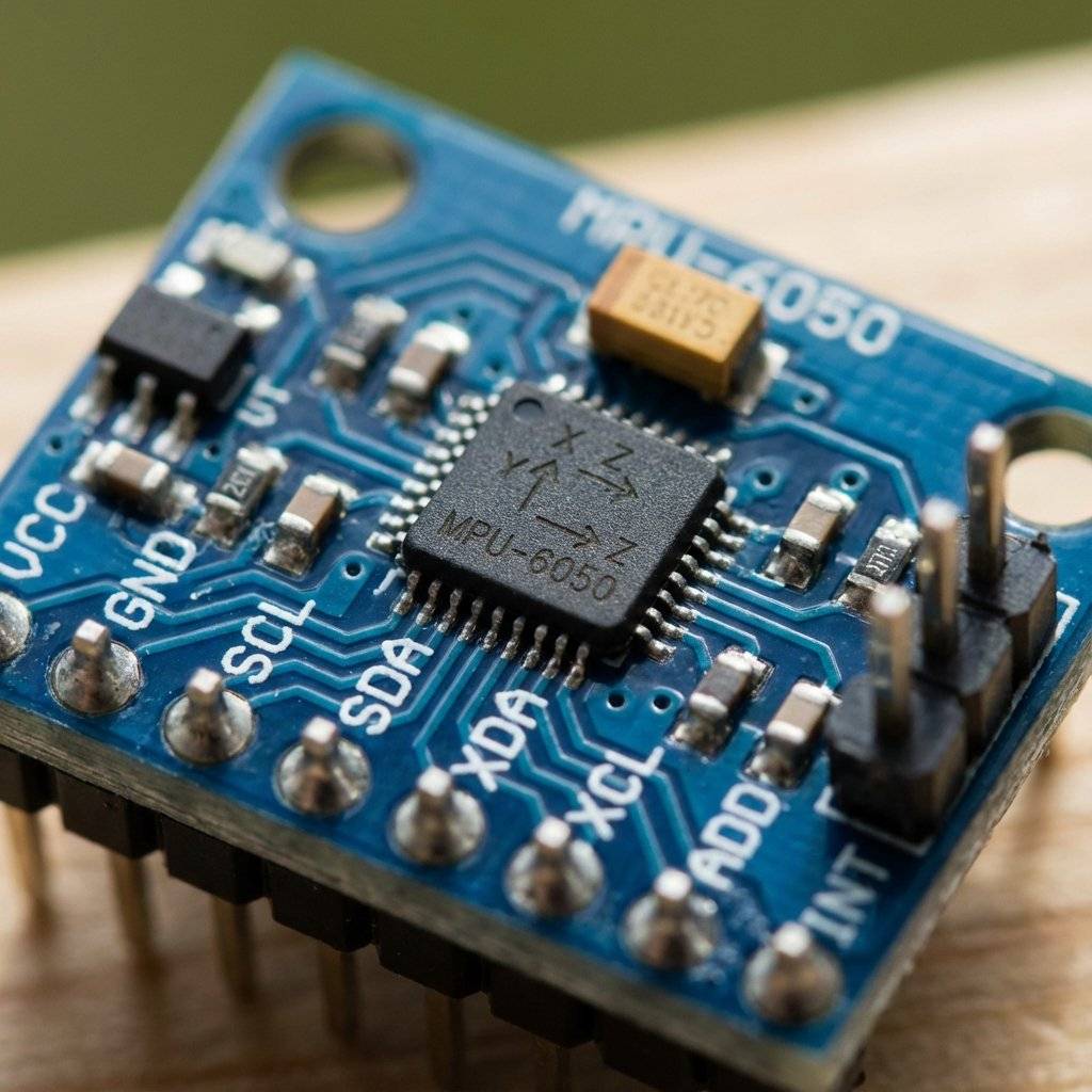
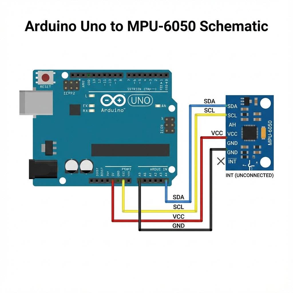
It’s painfully simple. I2C is famous for being easy to wire.
VCC -> 5V
GND -> GND
SDA -> A4 (Uno)
SCL -> A5 (Uno)
Note: On Arduino Mega, SDA is pin 20, SCL is pin 21. On Leonardo, they are separate pins.
Every I2C device has a 7-bit address. The MPU6050 usually lives at 0x68 (Hexadecimal). If you connect the AD0 pin to 5V, it moves to 0x69. This enables you to use TWO gyros on the same robot!
Binary to Hex:
11010000x68104
(We usually use Hex because it’s shorter).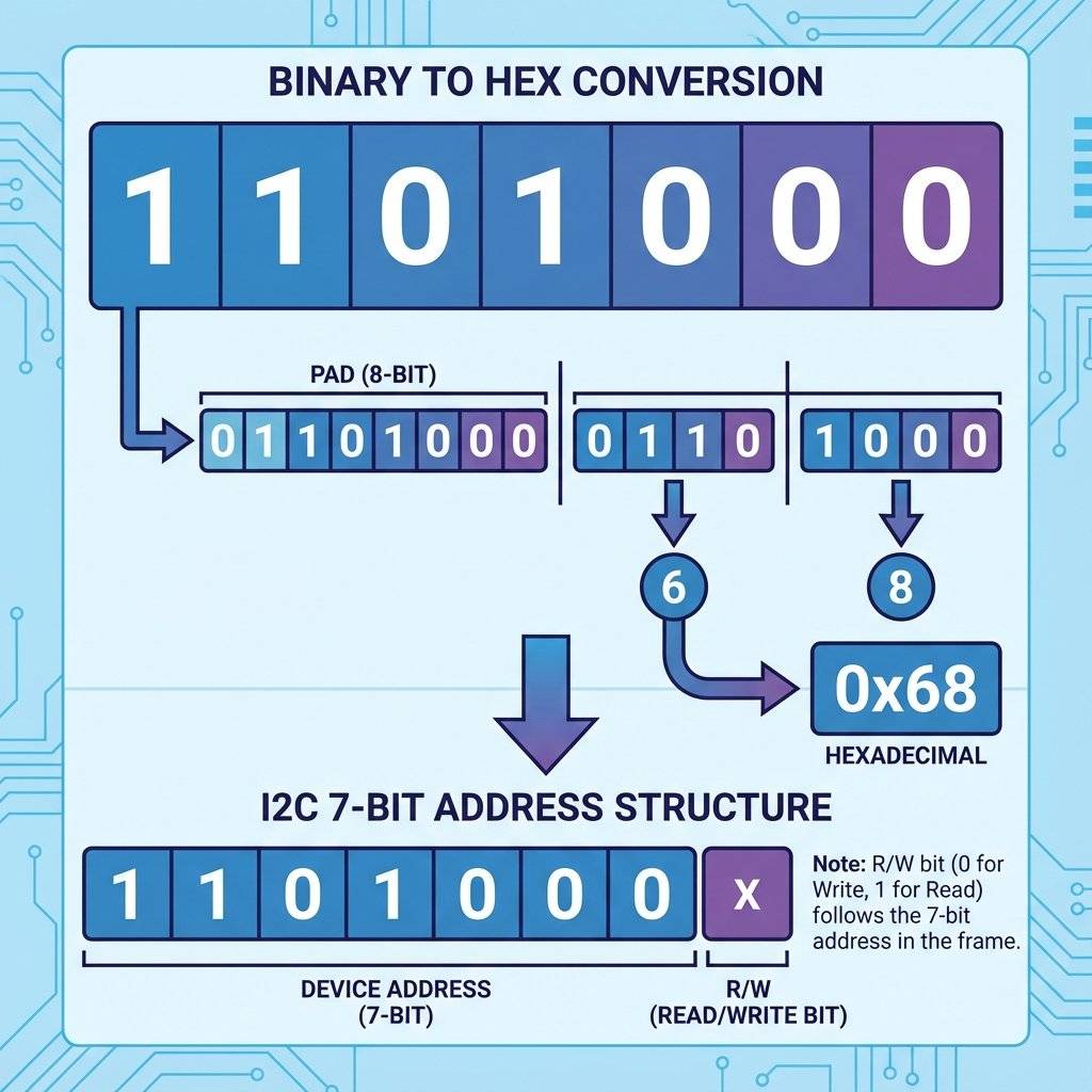
Inside the chip, there are typically 100+ “Registers”. Think of them as numbered lockers or mailboxes.

We don’t need a heavy library to verify it works. Let’s talk directly to the registers.
#include <Wire.h>

const int MPU_ADDR = 0x68; // I2C address of the MPU-6050

int16_t AcX, AcY, AcZ, Tmp, GyX, GyY, GyZ;

void setup() {
  Serial.begin(9600);
  Wire.begin();
// Wake up the MPU-6050 (It sleeps by default)
  Wire.beginTransmission(MPU_ADDR);
  Wire.write(0x6B); // Power Management Register
  Wire.write(0);    // Wake up!
  Wire.endTransmission(true);
}

void loop() {
  Wire.beginTransmission(MPU_ADDR);
  Wire.write(0x3B); // Start reading from register 0x3B (Accel X)
  Wire.endTransmission(false); // Restart connection, don't stop
  // Request 14 bytes (Accel X/Y/Z + Temp + Gyro X/Y/Z)
  Wire.requestFrom(MPU_ADDR, 14, true);
  // Read byte-by-byte
  // We combine High Byte (<<8) and Low Byte (|)
  AcX = Wire.read() << 8 | Wire.read();
  AcY = Wire.read() << 8 | Wire.read();
  AcZ = Wire.read() << 8 | Wire.read();
  Tmp = Wire.read() << 8 | Wire.read();
  GyX = Wire.read() << 8 | Wire.read();
  GyY = Wire.read() << 8 | Wire.read();
  GyZ = Wire.read() << 8 | Wire.read();
  // Print to Serial Plotter
  Serial.print("AccelX:"); Serial.print(AcX);
  Serial.print(",");
  Serial.print("AccelY:"); Serial.print(AcY);
  Serial.print(",");
  Serial.print("AccelZ:"); Serial.println(AcZ);
  delay(100);
}Line 35 is terrifying for new coders:
AcX = Wire.read() << 8 | Wire.read();
What is happening here?
The Problem: The acceleration value is a 16-bit number (e.g., 10,000). But I2C only sends 8 bits (1 byte) at a time.
The Split: The chip cuts the number in half. Top half (High Byte) and Bottom half (Low Byte).
The Reassembly:
Imagine holding two playing cards.
Wire.read() gets the first card (High Byte).<< 8 (Left Shift) moves it to the “Tens” place. It adds 8 zeros to the right.Wire.read() gets the second card (Low Byte).| (Bitwise OR) combines them. It pastes the Low Byte into those empty zeros.
This is arguably the most common line of code in embedded engineering. Memorize it.They sound similar, but they measure totally different things.
Accelerometer (The Joulemeter): Measures Force.
If you sit still, it measures 1G (Gravity) pointing down.
If you accelerate a car, it measures the force pushing you back in the seat.
Problem: It is VERY noisy. Every vibration shakes the data.
Gyroscope (The Spinner): Measures Rotation Speed (Degrees per Second).
If you sit still, it measures 0.
If you spin the board, it measures 300 deg/sec.
Problem: It Drifts. If you integrate the speed to find the angle, small errors add up. After 1 minute, it might think “Down” is “Left”.
To build a drone, you combine them.
You typically get values ranging from -17000 to +17000. Why negative? The chip uses Signed Integers (2’s Complement). If you tilt it Left, X is positive. Tilt Right, X is negative.
Let’s make this useful. We will use 4 LEDs (Up, Down, Left, Right) to show tilt.
AcX > 5000, light up RIGHT LED.AcX < -5000, light up LEFT LED.AcY > 5000, light up UP LED.AcY < -5000, light up DOWN LED.This is the exact same logic used in:
Game Controllers (Wiimote).
Drone Flight Controllers (Self-leveling).
VR Headsets.
// Simple Threshold Logic
if (AcX > 4000) {
  digitalWrite(RIGHT_LED, HIGH);
} else {
  digitalWrite(RIGHT_LED, LOW);
}

if (AcX < -4000) {
  digitalWrite(LEFT_LED, HIGH);
} else {
  digitalWrite(LEFT_LED, LOW);
}
// Repeat for Y axis...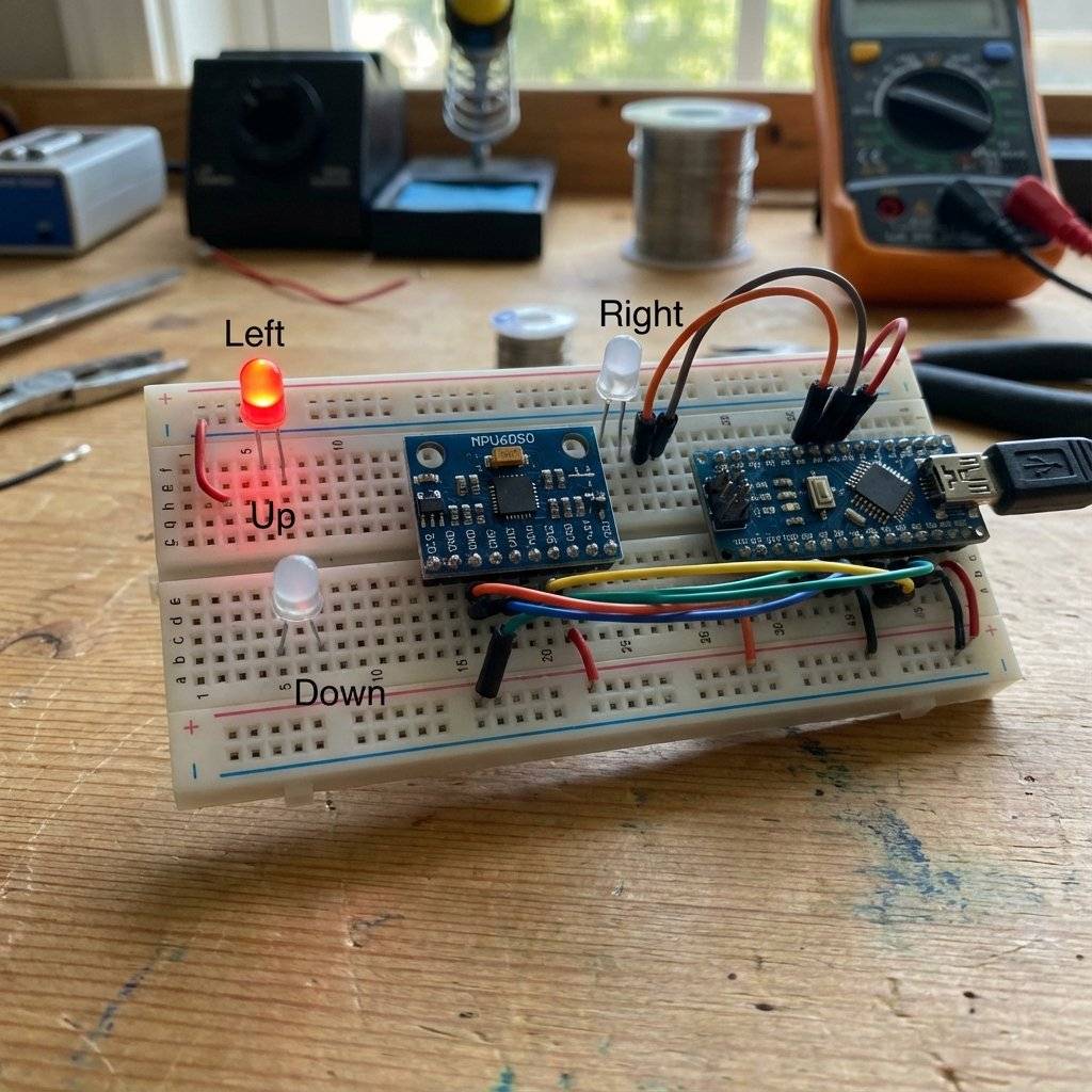
By default, the MPU6050 measures up to ±2G (Gravity). But what if you strap it to a rocket? 2G is nothing. We can hack Register 0x1C (ACCEL_CONFIG) to change the sensitivity.
Wire.beginTransmission(MPU_ADDR);
Wire.write(0x1C); // Access Accel Config
Wire.write(0x18); // Set to ±16G
Wire.endTransmission(true);
If you do this, your raw math changes. Instead of dividing by 16384 for 1G, you divide by 2048. Engineering is about trade-offs: Range vs Precision.
Polling the sensor in loop() is slow.
The MPU6050 has a “Data Ready” interrupt pin.
attachInterrupt(digitalPinToInterrupt(2), readData, RISING);The MPU6050 is a marvel of MEMS (Micro-Electro-Mechanical Systems). In the 1960s, the gyroscope for the Apollo moon mission was the size of a bucket and cost millions. It used spinning metal wheels. Today, we etch microscopic silicon “tuning forks” onto a chip for $3. When you rotate the chip, the vibration of these forks changes due to the Coriolis Effect. We measure that change as capacitance. It is literally a machine running inside a piece of silicon.
I mentioned the “Complementary Filter” (Easy math). If you want to work at NASA or SpaceX, you use a Kalman Filter. This is a complex algorithm that:
Kalman.h exist if you want absolute perfection.System Hangs: The Wire.requestFrom never returns.
Cause: Loose wire. If SDA/SCL disconnects, the Arduino waits forever.
Fix: Check connections. Use generic “I2C Scanner” code to verify address.
Values are erratic/noisy: Cause: Electrical noise or Motor vibration.
Fix: Use a “Complementary Filter” (Math) or just average 10 readings.
Address not found: Cause: AD0 pin is floating? Connect AD0 to GND for 0x68.
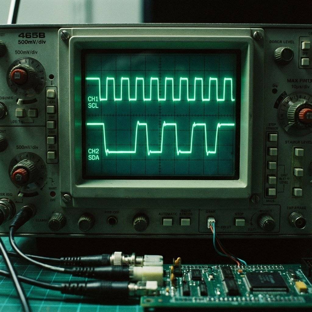
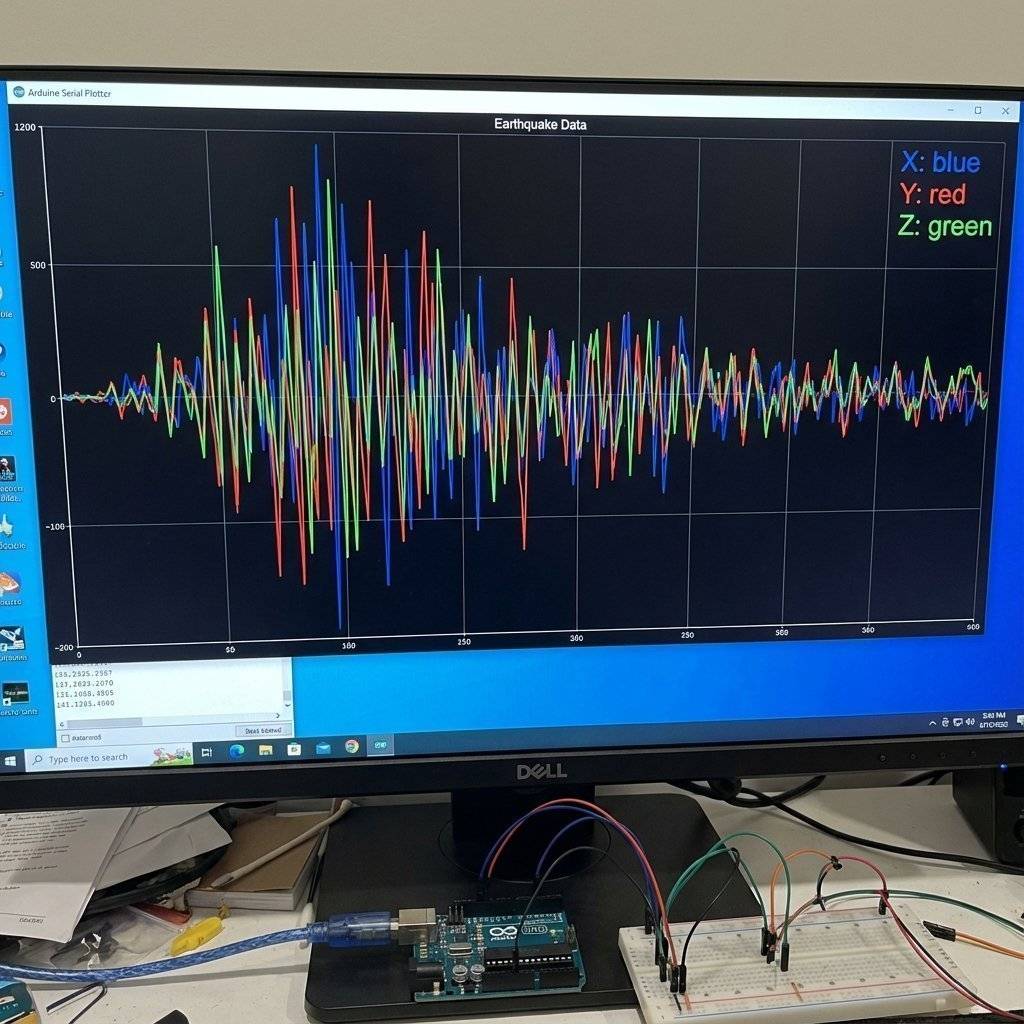
Open the Serial Plotter (Ctrl+Shift+L).
Shake the board.
You will see the waves react instantly.
Try to tap the table—you will see a sharp spike (Impact detection).
This is how your phone counts your steps (Pedometer)!
| Component | Quantity | Value | Notes |
|---|---|---|---|
| Arduino Uno | 1 | Any | The Brain. |
| MPU6050 | 1 | I2C | Accel/Gyro module. |
| Resistors | 2 | I2C Pull-ups. | |
| LEDs | 4 | Any | For tilt indicators. |
| Jumper Wires | 8 | M-F/M-M | Connectivity. |
You now speak specific dialect of “Chip Connect”. I2C is the industry standard for on-board communication. Because you know I2C, you can now use:
You are no longer limited by the pins on your Uno. You can chain 100 sensors together.
Next Up: We have inputs. We have outputs. We have protocols. Tomorrow, we learn Logic State. We will build a machine that remembers where it is in a sequence. See you on Day 25.

Digital is black and white. The real world is gray. Learn how to use the Arduino ADC to read potentiometers, sensors, and voltages using analogRead().
Read More →
Give your circuits eyes and ears. Learn how to use Light Dependent Resistors (LDRs), Thermistors, and Microphones to control the physical world.
Read More →