Motion Control: Master Arduino I2C and the MPU6050 Gyroscope
Learn how to read the MPU6050 Accelerometer and Gyroscope using the I2C protocol. Master registers, raw data, and build a digital spirit level.
Read More →
* SYSTEM.NOTICE: Affiliate links support continued laboratory research.
Welcome to Day 6. For the last 5 days, your circuits have been blind, deaf, and numb. They lived in a dark void. You pushed a button, and they obeyed. But they had no idea why. They didn’t know if it was day or night. They didn’t know if the room was on fire. They didn’t know if you were clapping your hands.
Today, that changes. Today, we give your circuits Senses. We represent the “Input” side of the “Input-Process-Output” model. We are going to build machines that convert Physics into Electricity.
How does a microchip “feel” light? It doesn’t have nerves. It only understands one thing: Voltage. To give it senses, we need a component that translates a physical quantity (Light, Heat, Sound) into a change in electrical resistance. These are called Transducers.
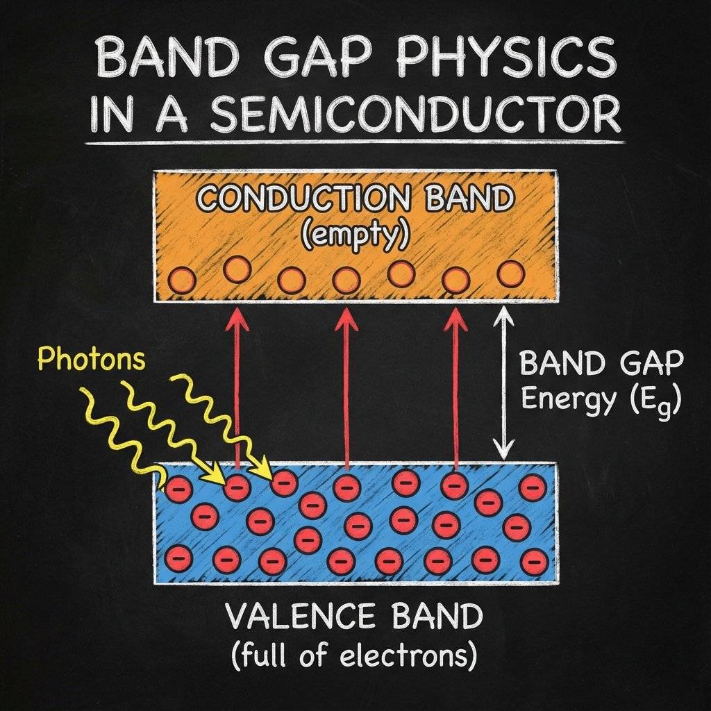
If you zoom in to the atomic level of the Cadmium Sulfide (CdS), you see electrons sitting in their “homes” (Valence Band). They are comfortable. They don’t want to move. To conduct electricity, they need to jump up to the “highway” (Conduction Band). But there is a gap. A Band Gap. It’s like a wide ditch.
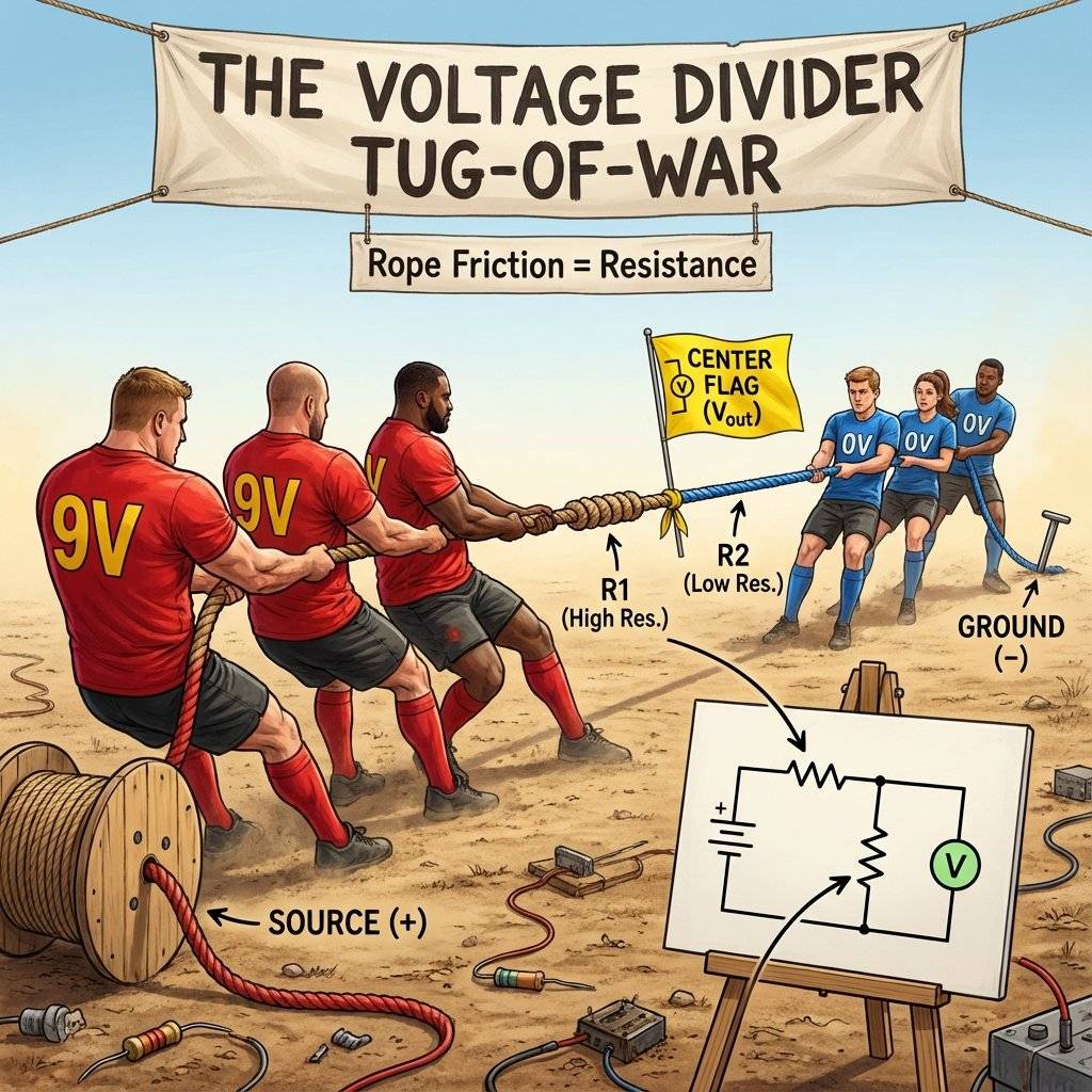
Stop. Do not skip this section. If you understand the Voltage Divider, you understand 90% of all sensors. If you don’t, you will spend your life confused why your sensors “don’t work”.
Sensors change their Resistance. But chips (and Arduinos) measure Voltage. You cannot just measure resistance directly. You can’t just plug an LDR into a battery and expect a signal. If you connect an LDR (Variable Resistor) to a battery:
We need to turn that changing Resistance into a changing Voltage. We do this by adding a second, fixed resistor. We put them in a line (Series). They fight over the voltage.
The Math (Because you need it):
Let’s plug in numbers. Scenario A: Darkness
Scenario B: Bright Light
See that swing? to . That is a massive signal. Your transistor (or Arduino) can see that clearly. If we didn’t use R1, the voltage would have stayed stuck at the whole time.
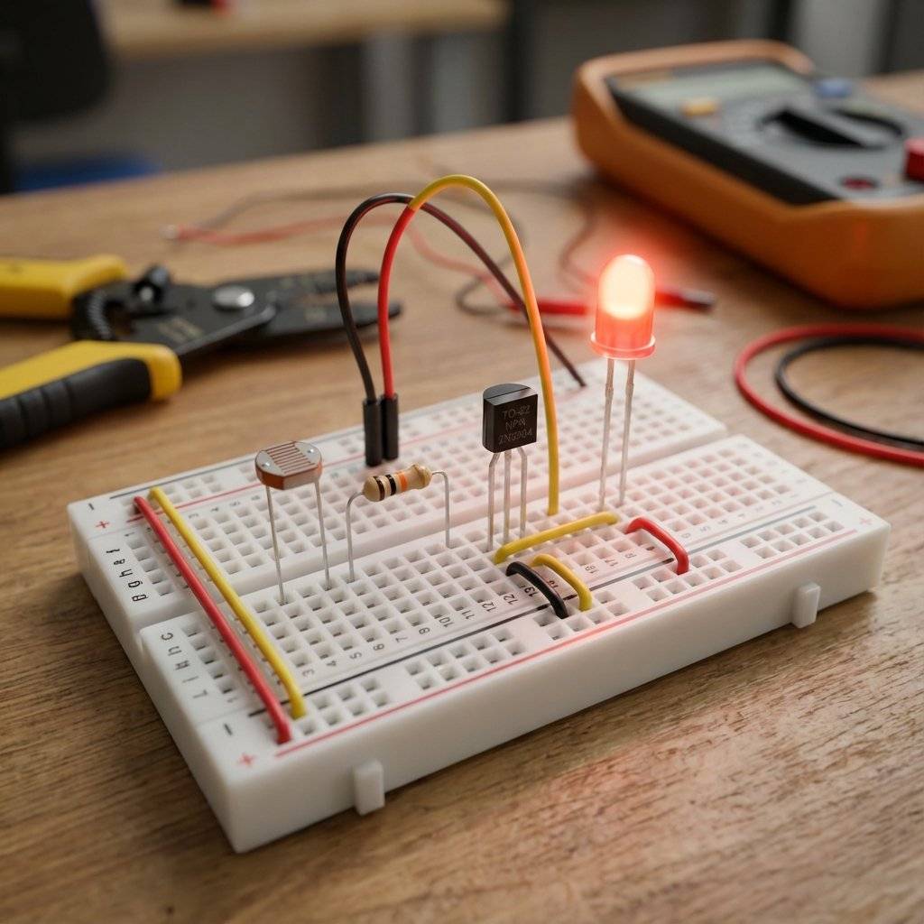
Also known as a Photoresistor. It looks like a flat disk with a squiggly red line on it. That line is Cadmium Sulfide (CdS), a material that hates darkness.
Pro Tip: Measure your specific LDR with a multimeter. Some range from to , others from to . Knowing your specific range helps you pick the perfect fixed resistor (aim for the “Geometric Mean” of the light and dark values).
We want a light that turns ON when it gets DARK. This is exactly what streetlights do.
We build a Voltage Divider with the LDR on the bottom (connected to Ground).
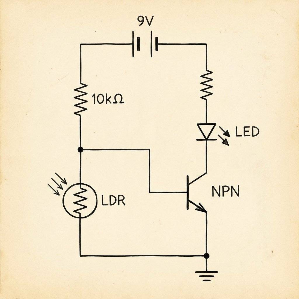
Cover the LDR with your finger. The LED should glow. You have just built a machine that reacts to a shadow.
What if it turns on too early (at twilight)? You need to adjust the balance of power in the Voltage Divider. The Rule: To make the sensor “win” easier (trigger earlier), give it a weaker opponent.
Have you ever seen a street light flicker on and off at sunset? It’s confused. It’s right on the edge. This is called “Chatter”. To fix this, engineers use Hysteresis. It means “History”. The turn-on point (e.g., ) is different from the turn-off point (e.g., ). This creates a “Safe Zone” where the light won’t flicker. We can’t do this easily with just a transistor, but we will learn how to do it with the LM393 Comparator Chip in a later post.
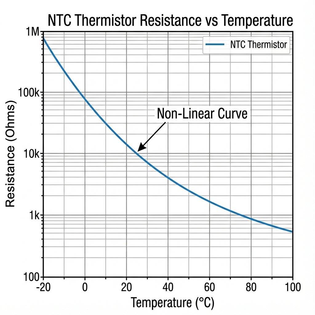
Temperature sensors are everywhere. Your phone, your car, your coffee maker. They are called Thermistors (Thermal Resistors). They look like small beads, often dipped in epoxy.
We will use an NTC.
Unlike a normal resistor which stays flat, an NTC curve looks like a ski slope. At room temperature (), it might be . In boiling water (), it might drop to .
Warning: It’s Non-Linear. The change isn’t a straight line. It’s an exponential curve. read exact degrees (like ), you need a complex Luckily, for a fire alarm, we don’t care about the exact degree. We just care about “HOT vs COLD”. The Voltage Divider is perfect for this.
Because the NTC curve is exponential, the voltage output won’t be a straight line.
How Engineers Fix This:
Hardware: Place a parallel resistor across the thermistor. This flattens the curve (S-Curve).
Software: Use a Look-Up Table (LUT). Instead of doing the complex log math on a tiny chip, we hard-code a table:
...
This makes the code 100x faster. We will use this technique in Week 3.
One Flaw: Self-Heating. If you put too much current through a thermistor, it warms up (because ). This fake heat messes up your reading! To fix this, keep the current very low (use a high value fixed resistor).
We want an alarm (Buzzer) to sound when it gets HOT. This is similar to the Night Light, but we need to swap the positions in the Voltage Divider. Why? Because we used an NTC.
When the Thermistor gets hot, its resistance drops, allowing more current to flow from +Vcc to the center point, raising the voltage.
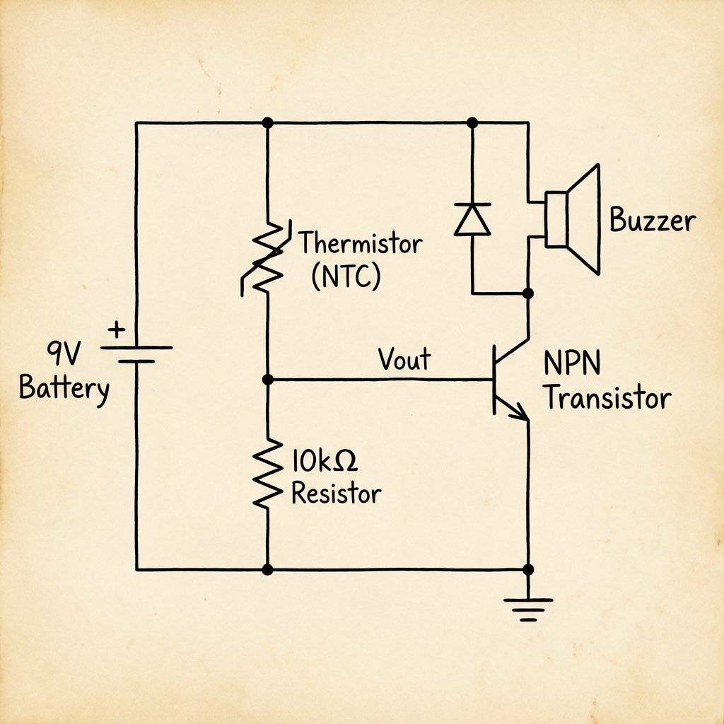
The Build:
Light and Heat are slow. Sound is fast. Sound is vibration. To sense sound, we need a component that vibrates.
Inside that tiny silver canister is a drum skin (Diaphragm). It is one half of a capacitor. When you talk, the sound waves hit the drum skin, moving it closer/further from the backplate. This changes the Capcitance. And thanks to a tiny JFET transistor hidden inside the metal can, this change in capacitance becomes a change in voltage.
Electret vs Dynamic:
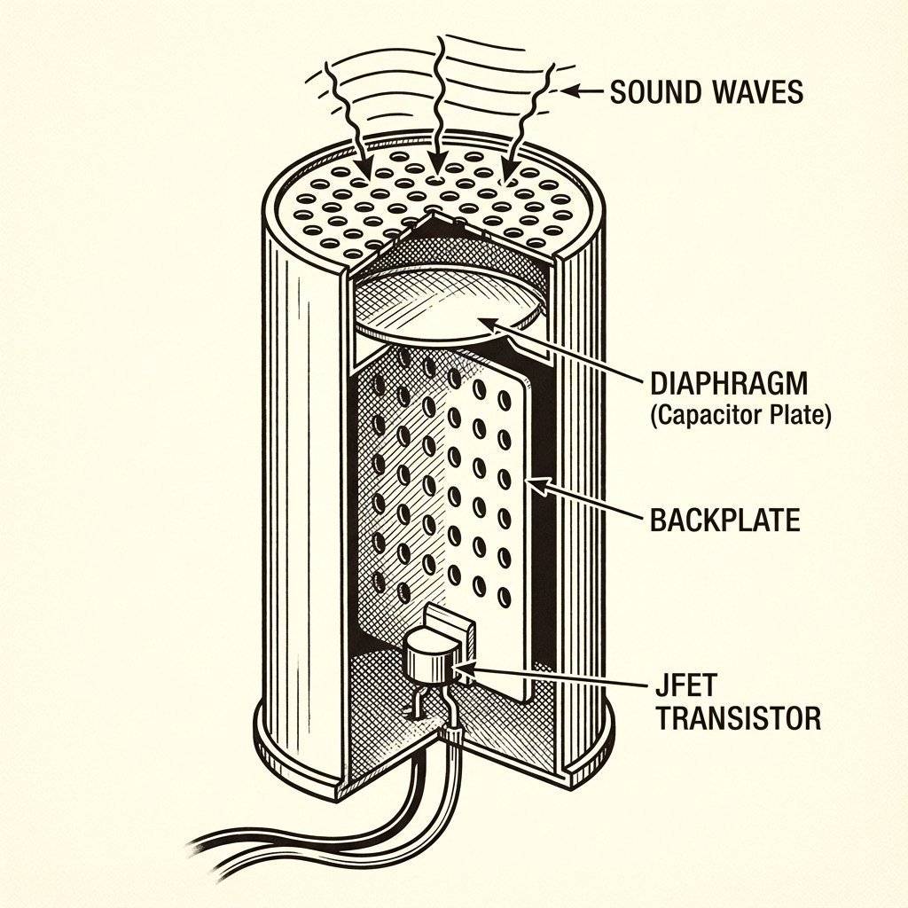
Unlike the LDR (which gives a steady DC voltage), a Microphone gives an AC Waveform riding on top of a DC voltage. It’s a tiny wiggle. To use it, you usually need an Amplifier (like an Op-Amp) to make the signal big enough for a digital chip to see. We will tackle Op-Amps next week. For now, know that the Microphone is just a sensor that turns Air Pressure into Voltage Wiggles.
We have touched on a huge topic today. Analog.
The real world is Analog. Your computer is Digital. Sensors are the bridge. The “Voltage Divider” is the tool that formats the Analog world into a language (Voltage) that we can process.
You interact with these sensors a hundred times a day.
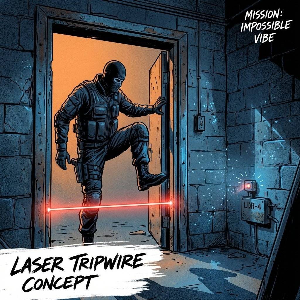
Time for a spy movie gadget. Goal: An alarm that goes off when a laser beam is broken.
Recipe:
Bonus Hard Mode: Make it “Latch”. With a simple transistor, the alarm stops as soon as the person walks past. Can you use a 555 Timer (from Day 5) or a Flip-Flop arrangement to make the alarm stay on until you reset it?
If you want to think like a thief (to build better security), how would you beat this?
Sensors are messy.
You built the Night Light. But it turns on at 4 PM, not 8 PM. You need to Calibrate.
Golden Rule: The fixed resistor should roughly equal the sensor resistance at the “Trigger Point”.
| Component | Measures | Type | Key Rule |
|---|---|---|---|
| LDR | Light | Resistive | Dark = High Resistance |
| Thermistor (NTC) | Heat | Resistive | Hot = Low Resistance |
| Microphone | Sound | Capacitive | Needs an Amplifier |
| Voltage Divider | — | — | Essential for all sensors |
Time to go shopping (or digging in your kit).
| Component | Value | Quantity | Notes |
|---|---|---|---|
| LDR | GL5528 | 1 | Any generic photocell works. |
| Thermistor | 10k NTC | 1 | ”Negative Temperature Coefficient”. |
| Transistor | 2N2222 | 1 | Or BC547. |
| Resistors | , | 5 | For the Voltage Divider. |
| Potentiometer | 1 | For tuning sensitivity. | |
| LED | Any Color | 1 | Indicator. |
| Battery | 1 | Power source. |
Transducer: A device that converts one form of energy (Light) into another (Electricity).
Voltage Divider: A circuit that splits voltage based on the ratio of two resistors.
NTC: Negative Temperature Coefficient (Hotter = Lower Resistance).
LDR: Light Dependent Resistor.
Hysteresis: A lag between input and output to prevent “chatter”.
Analog: A continuous signal with infinite resolution.
Most sensors are delicate. Maximum current for an LDR is usually . If you connect it directly to a battery without a fixed resistor, and you shine a bright light on it… Resistance drops to near zero -> Current spikes -> Smoke. Always, always use a fixed resistor in series.
Before today, your circuits were isolated. They existed in a theoretical world of perfect 9V and 0V. Today, you let the chaos of the real world in. Light is messy. Heat is unpredictable. But by embracing this chaos, your circuits became alive. They can react. They can adapt. This is the difference between a calculator and a robot.
We have sensed the world. Now we need to make decisions based on it. Tomorrow, we learn about Logic Gates. AND, OR, NOT, NAND. The building blocks of computers. We will build a machine that only unlocks if two people turn their keys at the same time: The Digital Logic Lock. Get your push buttons ready. The world is about to get logical.
Q: Can I use a sensor without a resistor? A: No. A resistive sensor needs a “pull” partner to create a voltage difference. Without it, you just have a variable blockage with constant voltage.
Q: My LDR readings are jumping around. A: Welcome to the real world. Light isn’t constant. Shadows move. Dust floats. You might need “Hysteresis” (a gap between on/off thresholds) which we will learn with Op-Amps.
Q: Do I need a specific LDR? A: Most cheap hobby LDRs are the “GL55xx” series. They are interchangeable for these basic circuits.
P.S. Your circuit is now watching you. Don’t be alarmed. It’s just a rock that learned to see.

Learn how to read the MPU6050 Accelerometer and Gyroscope using the I2C protocol. Master registers, raw data, and build a digital spirit level.
Read More →
Digital is black and white. The real world is gray. Learn how to use the Arduino ADC to read potentiometers, sensors, and voltages using analogRead().
Read More →