Real robots don’t wait.
Does your car’s airbag wait for the radio to finish changing the station? No.
To build professional-grade systems, you need to change how you think.
You need to stop writing “Linear Code” and start building State Machines.
Imagine a chef.
He puts pasta in boiling water (10 mins) and stands there staring at it.
He does nothing else.
That is delay(600000).
It blocks the CPU. You cannot read buttons. You cannot blink LEDs. You are paralyzed.
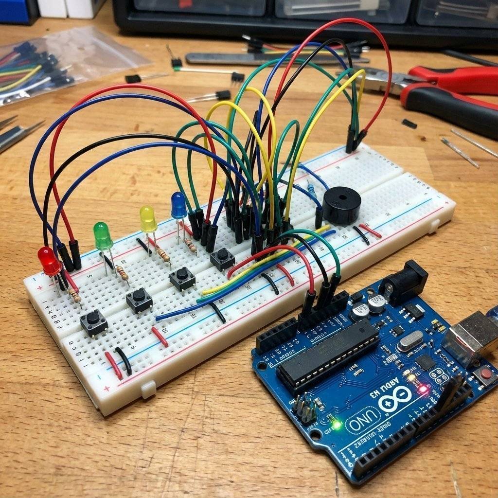
We need 4 pairs of Inputs and Outputs.
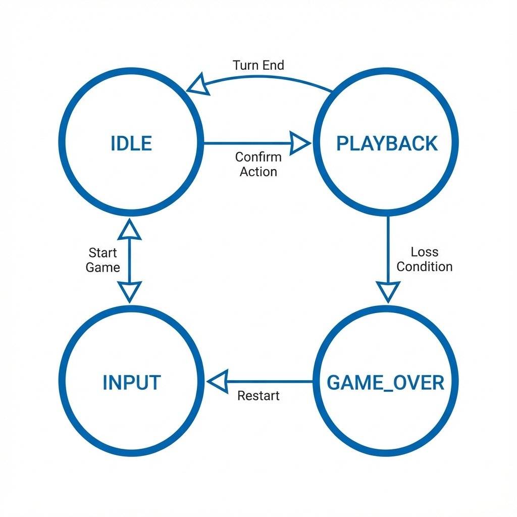
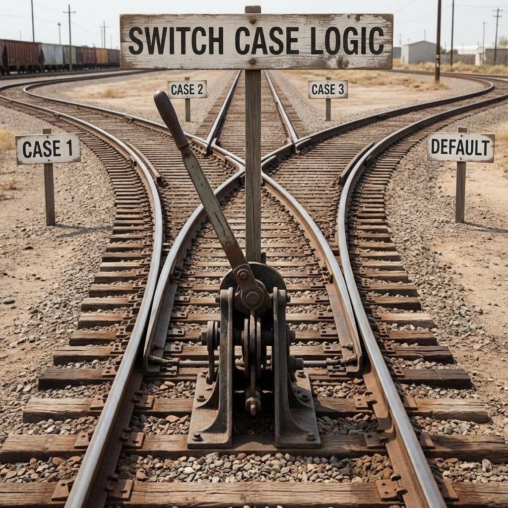
The Architecture: Finite State Machines (FSM)
Don’t write one giant loop. Break your system into States.
For our game, we have 4 clear distinct modes:
- IDLE: Waiting for start.
- PLAYBACK: Showing the sequence.
- INPUT: Waiting for user.
- GAME_OVER: Failed state.
We use a “Switch Case” to jump between these tracks.
The Code: Professional Structure
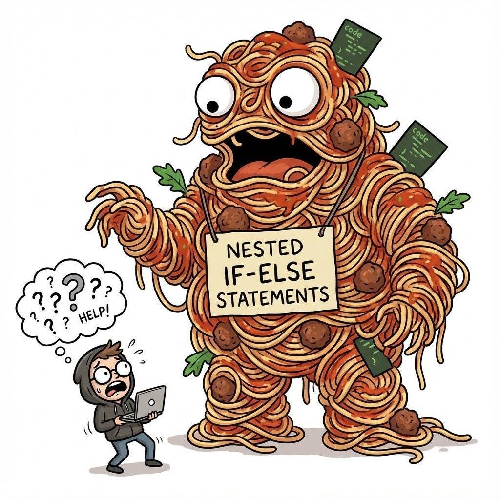
We are leaving “Spaghetti Code” behind.
We will use Enums to name our states.
Step 1: Defining the States
// Define the States
enum GameState {
IDLE,
PLAYBACK,
INPUT,
GAME_OVER
};
GameState currentState = IDLE;
// Hardware Definitions
const int leds[] = {8, 9, 10, 11};
const int buttons[] = {2, 3, 4, 5};
const int buzzer = 12;
// High Score Memory
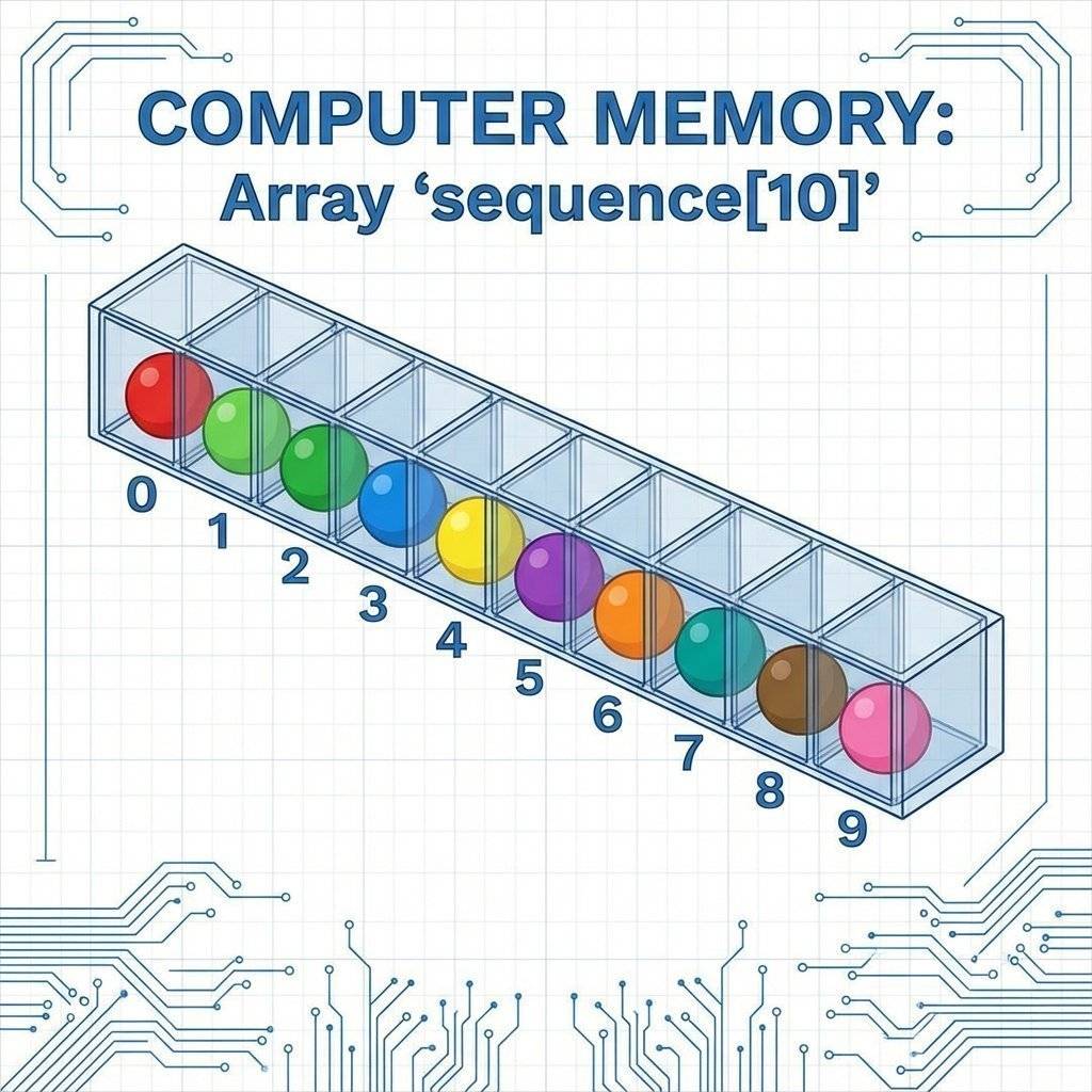
int sequence[100]; // Max 100 turns
int turn = 0; // Current turn count
int step = 0; // Player's step in current turn
void setup() {
Serial.begin(9600);
// Initialize Pins using Loops (Professional Style)
for (int i = 0; i < 4; i++) {
pinMode(leds[i], OUTPUT);
pinMode(buttons[i], INPUT_PULLUP); // Enable internal resistors
}
pinMode(buzzer, OUTPUT);
pinMode(6, INPUT_PULLUP); // Start Button
// True Randomness
randomSeed(analogRead(A0));
Serial.println("System Ready. Press Start.");
}
Step 2: The Main Loop (The “Brain”)
This is the beauty of FSM. The loop is clean.
It just asks: “What state am I in?” and delegates the work.
void loop() {
  switch (currentState) {
    case IDLE:
      // Pulse LEDs comfortably
      // Check for Start Button
      if (digitalRead(6) == LOW) {
        startGame();
      }
      break;
    case PLAYBACK:
      playSequence();
      currentState = INPUT; // Done playing, your turn!
      break;
    case INPUT:
      readPlayerInput();
      break;
    case GAME_OVER:
      playLosingSound();
      currentState = IDLE;
      break;
  }
}
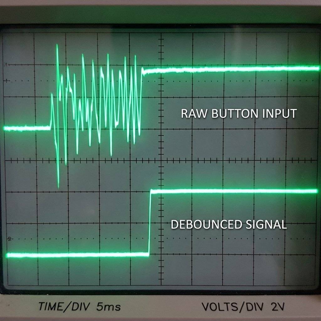
When you press a metal button, it doesn’t just “click”.
Microscopically, it bounces thousands of times in 1 millisecond.
The Arduino is fast enough to count 50 clicks for one press.
This crashes games.
The Fix:
- Hardware Debouncing: Add a capacitor (100nF).
- Software Debouncing: Ignore changes faster than 50ms.
- Read Button.
- If changed? Wait 50ms.
- Read Again.
- Still pressed? It’s real.
// Simple Software Debounce Snippet
if (digitalRead(btn) == LOW) {
  delay(50); // Wait for bounce to settle
  if (digitalRead(btn) == LOW) {
// Valid Press!
// Wait for release so we don't register 10 presses for one hold
while(digitalRead(btn) == LOW);
  }
}
Note: The while loop technically blocks code, but for a game like Simon where specific input is required, it is acceptable. In a flight controller, you would avoid this.
Implementing the Game Logic
This is where arrays shine.
We generate a random number (0-3) and store it in sequence[].
Each turn, we loop through the array.
The Playback Function
void playSequence() {
  delay(500);
  for (int i = 0; i < turn; i++) {
    int colorID = sequence[i];
    digitalWrite(leds[colorID], HIGH);
    tone(buzzer, 200 + (colorID * 100)); // Different pitch for each color
    delay(300);
    digitalWrite(leds[colorID], LOW);
    noTone(buzzer);
    delay(100);
  }
}
We need to wait for the user to press something.
- If press WRONG -> GAME_OVER.
- If press RIGHT -> Check next step.
- If finish sequence -> Level up.
void readPlayerInput() {
  // Check all 4 buttons
  for (int i = 0; i < 4; i++) {
    if (digitalRead(buttons[i]) == LOW) {
      // Debounce here...
      // Did they act correctly?
      if (i == sequence[step]) {
        // Correct!
        step++;
        flashLED(i); // Feedback
      } else {
        // Wrong!
        currentState = GAME_OVER;
        return;
      }
    }
  }

  // Did they finish the turn?
  if (step >= turn) {
    turn++;        // Level Up
    step = 0;      // Reset steps
    sequence[turn-1] = random(0, 4); // Add new color
    currentState = PLAYBACK;
  }
}

// Helper Function to Flash LED
void flashLED(int id) {
  digitalWrite(leds[id], HIGH);
  tone(buzzer, 300 + (id * 200));
  delay(200);
  digitalWrite(leds[id], LOW);
  noTone(buzzer);
  delay(100);
}
Challenge: The “Evil” Mode
Once you have the basic game working, you can add “Modes”.
- Speed Up: Decrease delay as level increases.
- Reverse Mode: Enter sequence backwards.
- Distraction Mode: Randomly flash dummy LEDs.
int delayTime = 500 - (turn * 20); // Faster every turn
if (delayTime < 100) delayTime = 100; // Cap limit
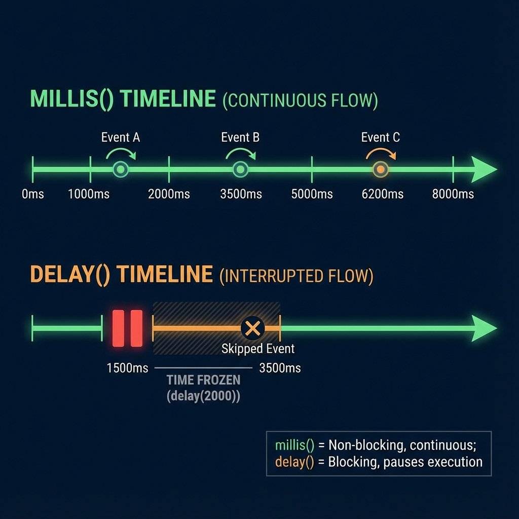
Advanced: Adding “Millis” Timers
In the code above, I used delay(300) for simplicity.
To impress an interviewer, you would remove that.
You would have a variable lastFlashTime and check:
if (millis() - lastFlashTime > 300)
This allows you to animate a background “score counter” on an LCD while the game is playing.
Troubleshooting
- Randomness isn’t Random: Use
randomSeed(analogRead(A0)) in setup.
- Buttons triggering twice: Increase debounce time.
- Low LED brightness: Check resistor values (220Ω vs 10kΩ).
- Buzzer clicking: Ensure you are using
tone().
- Game crashes after 100 turns: Buffer overflow. Check turn count.
The Engineer’s Glossary (Day 25)
- FSM: A model with defined states and transitions.
- Blocking Code: Code that pauses the processor (e.g.,
delay()).
- Non-Blocking Code: Code that checks conditions (e.g.,
millis()).
- Debounce: Filtering out mechanical noise from a switch.
- Enum: Named constants for readability.
Conclusion
You have just built a State Machine.
- Idle -> Playback -> Input -> Win/Loss.
This architecture is scalable.
You can add a “High Score” state. A “Cheat Mode” state.
You just draw a new circle on the chart and add a
case in the switch.
This is how ATMs work. This is how vending machines work.
This is how code becomes reliable.
Next Up:
We have mastered logic. Now we need to talk to the outside world.
Not just blinking lights, but meaningful data.
Tomorrow, we learn Serial Communication properly.
Converting data types, parsing strings, and talking to Python.
See you on Day 26.


